
Polymer/liquid crystal composite and liquid crystal element

Inactive Publication Date: 2008-11-13
JNC PETROCHEM +2
View PDF5 Cites 37 Cited by
  • Summary
  • Abstract
  • Description
  • Claims
  • Application Information

AI Technical Summary

Benefits of technology

[0200]The composite material of the invention can also be produced by mixing the liquid crystal composition B (liquid crystal material of the invention) with a polymer obtained in advance by means of polymerization. Preferably, the composite material is produced by mixing the liquid crystal composition B with a low-molecular-weight monomer, macromonomer, oligomer or the like (hereinafter collectively referred to as “monomer and the like”), which is converted to a polymer, and thereafter by conducting polymerization reaction in the mixture. In the specification, a mixture including the monomer and the like and the liquid crystal composition B is referred to as “polymerizable monomer / liquid crystal mixture.” Depending on the necessity, the “polymerizable monomer / liquid crystal mixture” may contain a polymerization initiator, a curing agent, a catalyst, a stabilization agent, a dichroism pigment, a photochromic compound or the like within a range in which the effects of the invention are not reduced, as described later. For example, depending on the necessity, the polymerizable monomer / liquid crystal mixture of the present invention may contain a polymerization initiator in an amount of approximately 0.1 to approximately 20 parts by weight per 100 parts by weight of the polymerizable monomer.
[0201]Polymerization temperature is preferably a temperature at which the polymer / liquid crystal composite shows high transparency and isotropic nature. More preferably, polymerization is started at a temperature at which a mixture of the monomer and the liquid crystal material exhibits the isotropic phase or the blue phase and is terminated in the state of the isotropic phase or the optically isotropic liquid crystal phase. That is, polymerization temperature is preferably a polymerization temperature at which, after polymerization, the polymer / liquid crystal composite does not substantially scatter light which is nearer to the long-wavelength side compared to the visible light and exhibits an optically isotropic state.
[0202]For example, a low-molecular-weight monomer, macromonomer and oligomer can be used as a raw material monomer of a polymer constituting the composite material of the invention. In the present specification, the phraseraw material monomer of a polymer” is intended to include a low-molecular-weight monomer, macromonomer, oligomer and the like. Further, a polymer to be obtained preferably has a three-dimensional cross-linked structure. Therefore, as a raw material monomer of a polymer, a multifunctional monomer having 2 or more polymerizable functional groups is preferably used. The polymerizable functional group is not particularly limited, and examples thereof include an acryl group, a methacryl group, a glycidyl group, an epoxy group, an oxetanyl group, a vinyl group and the like. From the viewpoint of polymerization velocity, an acryl group and a methacryl group are preferred. In a raw material monomer of a polymer, approximately 10 wt % or more of a monomer having 2 or more polymerizable functional groups is preferably contained since the composite material of the invention tends to easily show high transparency and isotropic nature thereby.
[0203]Further, in order to obtain a suitable composite material, a polymer preferably has a mesogenic moiety. A raw material monomer having a mesogenic moiety can be used as a part or all of the raw material monomer of the polymer.
[0204]2.1. Monofunctional / Bifunctional Monomer Having a Mesogenic MoietyRa—Y-(AM-ZM) p-AM-Y—Rb   (M1)Rb—Y-(AM-ZM) p-AM-Y—Rb   (M2)
[0205]In formula (M1), Ra is each independently hydrogen, halogen, —CN, —N═C═O, —N═C═S or alkyl having 1 to 20 carbon atoms, wherein any —CH2— in the alkyl can be substituted with —O—, —S—, —CO—, —COO—, —OCO—, —CH═CH—, —CF═CF— or —C≡C—, and any hydrogen in the alkyl can be substituted with halogen or —CN.

Problems solved by technology

However, though an optically isotropic liquid crystal phase is exhibited in a wide temperature range in the case of such a composite material, there is a problem that birefringence may remain even if returning to a liquid crystalline state, in which electric field is not applied, after application of high electric field.
Therefore, in the case of liquid crystal elements such as indicating element, use of a composite material with a polymer is limited.

Method used


Image

  • Polymer/liquid crystal composite and liquid crystal element
  • Polymer/liquid crystal composite and liquid crystal element
  • Polymer/liquid crystal composite and liquid crystal element

Examples


example 1

[0272]Preparation of Liquid Crystal Composition

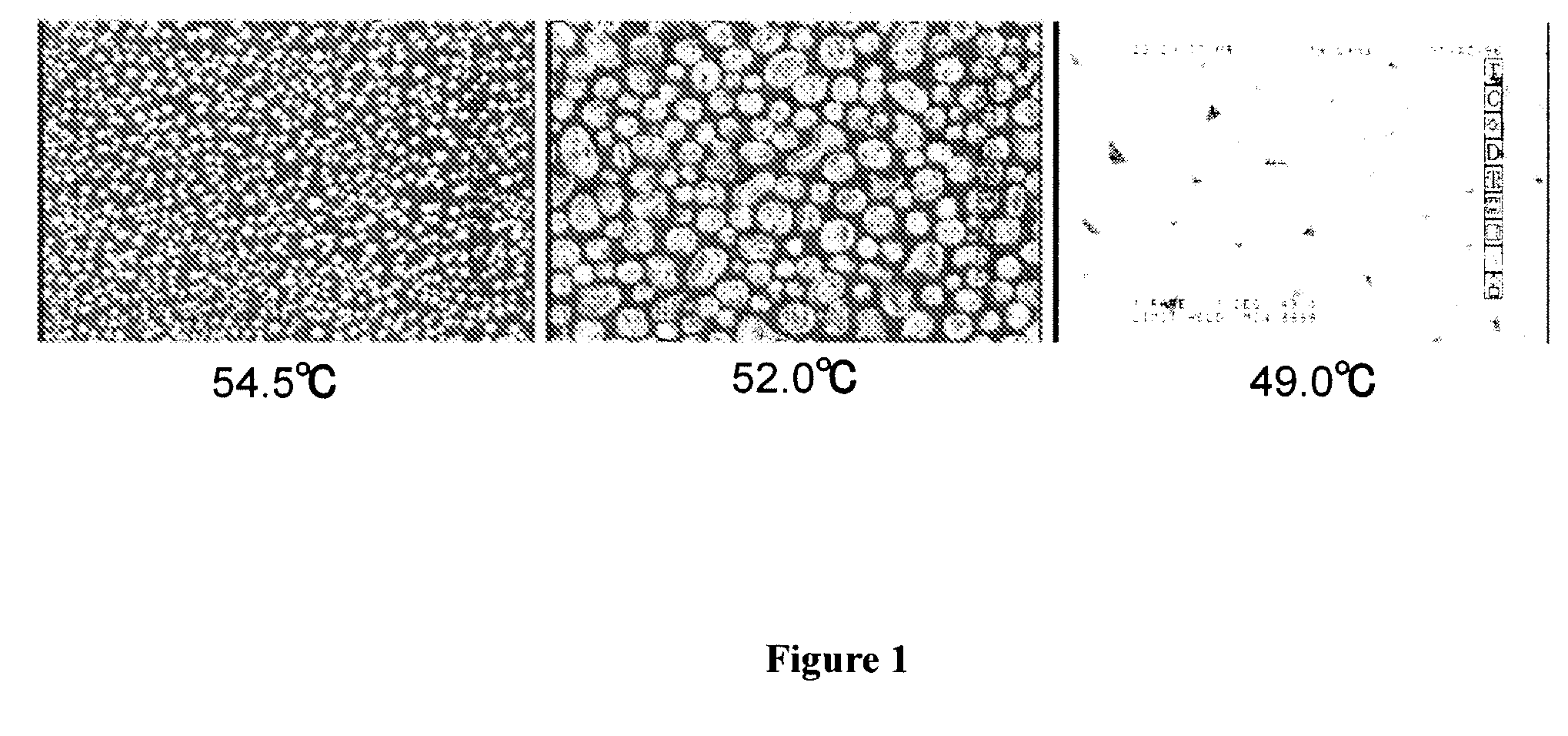
[0273]A nematic liquid crystal composition A-1 was prepared by mixing compounds represented by the following formulae (a) to (f) and (g) in the weight ratio shown below. Specifically, the composition was prepared by mixing: compounds (a) and (b) having the clearing point (N-I point) of 250° C. or more, as compounds corresponding to the component 1 represented by the above-described formula (1); compound (g) having the K-I point of 49.8° C. and the clearing point of 7.7° C., as a compound corresponding to the component 2 represented by the above-described formula (3); and compounds (c) to (f). Values shown at the right side of values of the weight ratio are phase transition temperatures of respective compounds. The clearing point of the compound (g) was 7.7° C. The clearing point of the composition was given as an extrapolation value of N-I point, which was measured after mixing 15 wt % of compound (g) with the mother liquid crystal ZLI-...

example 2

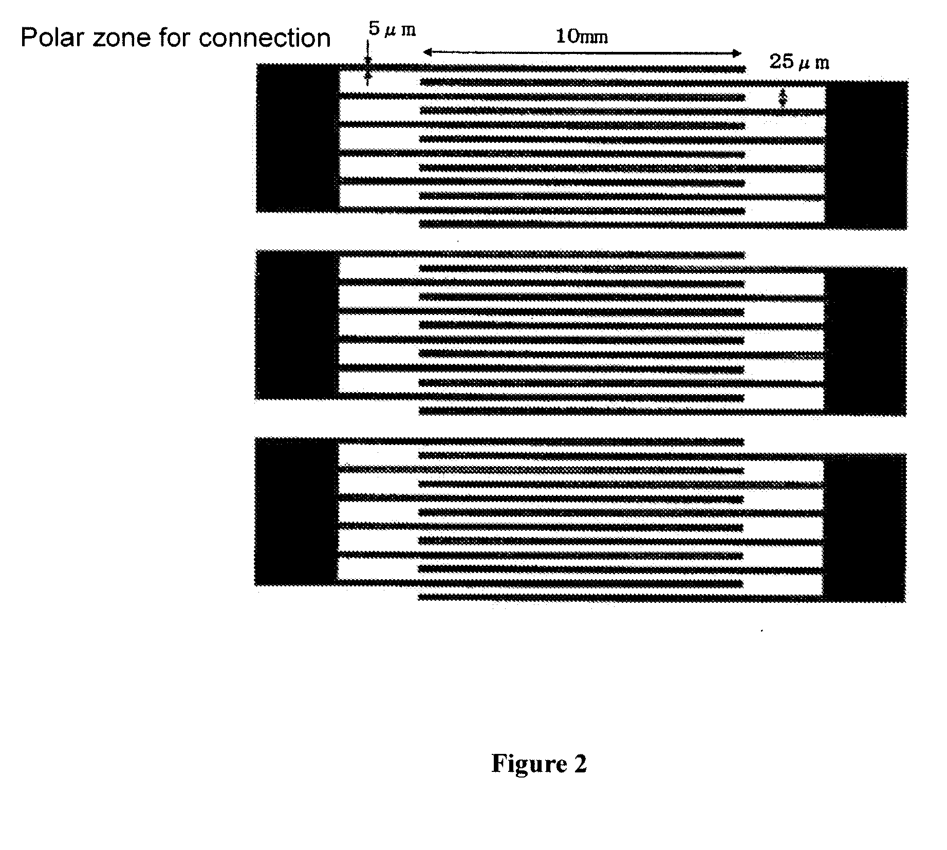
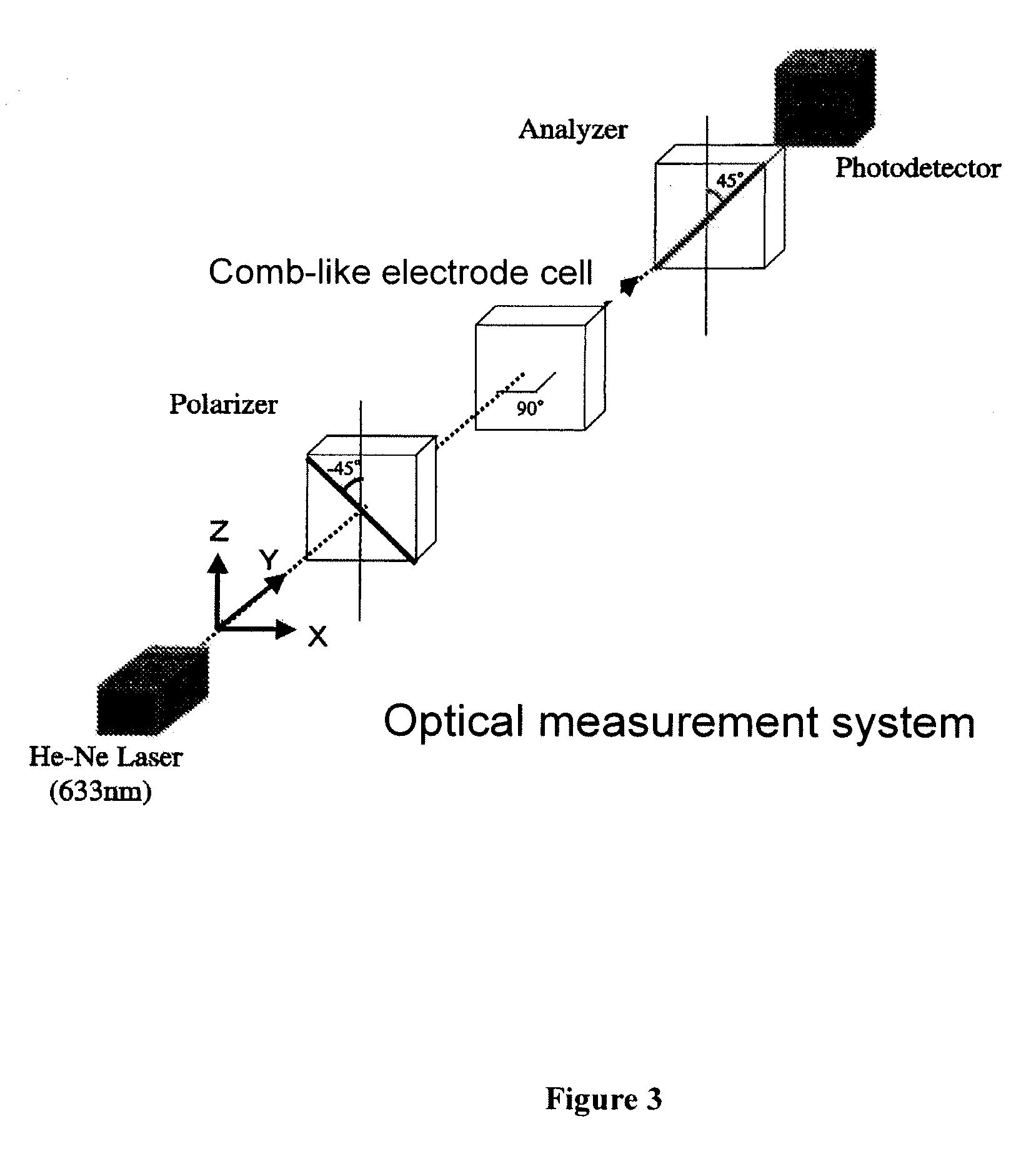
[0289]A cell in which the polymer / liquid crystal composite A-5P obtained in Example 1 was held was set the optical system shown in FIG. 3 to measure electrooptic characteristics. The aforementioned cell was set in the optical system so that the incidence angle of laser light was perpendicular to the cell surface and the line direction of the comb-like electrode was 45° with respect to polarization plates of Polarizer and Analyzer, respectively. When a rectangular wave having the amplitude of 180 V was applied, the transmission rate was 88% at a measurement temperature of 20° C., and the transmitted light intensity was saturated. When detected using a photodetector, the transmitted light intensity at the time when no electric field was applied was 0.08, and the transmitted light intensity at the time when electric field was applied was 252. When the contrast was calculated, it was 3150. The response speed during rise time (time required for change of transmitted light intensity from ...

example 3

[0292]Preparation of Liquid Crystal Composition

[0293]A nematic liquid crystal composition F-1 was prepared by mixing compounds represented by the following formulae (o-1), (o-2), (o-3) and (p) in the weight ratio described below. Specifically, the composition was prepared by mixing: compounds (o-1) to (o-3) having the N-I point (clearing point) of 250° C. or higher, as compounds corresponding to the component 1 represented by the above-described formula (1); and compound (p) having the K-I point of 21.4° C. and the clearing point (extrapolation value) of −41.6° C., as a compound corresponding to the component 2 represented by the above-described formula (3). Values shown at the right side of values of the weight ratio are phase transition temperatures of respective compounds.

(o-1)16.6%K 102.9 N 258.7 I(o-2)16.7%K 98.4 N 255.2 I(o-3)16.7%K 87.8 N 251.5 I(p)50.0%K 21.4 I

[0294]Next, a chiral dopant ISO-6OBA2 was added to the liquid crystal composition F-1 to obtain liquid crystal compo...


PUM


Abstract

The invention is generally related to a polymer / liquid crystal composite, which includes a liquid crystal material which exhibits an optically isotropic liquid crystal phase in the temperature range of approximately 5° C. or more in the elevated temperature process but does not exhibit a nematic phase; and a polymer, and which is used for an element driven in a state of the optically isotropic liquid crystal phase.

Description

[0001]This application claims priority under 35 U.S.C. §119 to Japanese Patent Application Nos. JP 2007-123522 (filed May 8, 2007) and 2008-117127 (filed Apr. 28, 2008) each which applications is expressly incorporated herein by reference in its entirety.BACKGROUND OF THE INVENTION[0002]1. Field of the Invention[0003]The invention relates to a liquid crystal material contained in a polymer / liquid crystal composite including the liquid crystal material and a polymer for use in an element driven in a state of an optically isotropic liquid crystal phase, wherein the liquid crystal material exhibits the optically isotropic liquid crystal phase in the temperature range of approximately 5° C. or more in the elevated temperature process but does not exhibit a nematic phase; and a mixture comprising a liquid crystal material and a monomer, the polymer / liquid crystal composite and a liquid crystal element using the composite thereof.[0004]2. Related Art[0005]When a nematic liquid crystal com...

Claims


Application Information

Patent Timeline
IPC IPC(8): C09K19/12C09K19/52C09K19/00C09K19/06
CPCC09K19/0275C09K19/42Y10T428/10C09K19/586C09K19/588C09K19/544C09K2323/00
Inventor KIKUCHI, HIROTSUGUHASEBA, YASUHIRO
Owner JNC PETROCHEM
Learn More