
Electro-Blotting Devices, Systems, and Kits, And Methods For Their Use

a technology of electroblotting and electroblotting solution, applied in the direction of fluid pressure measurement, liquid/fluent solid measurement, peptide measurement, etc., can solve the problems of time-consuming methods, inconvenient and time-consuming methods, and disadvantages of requiring preparation and handling of liquid buffer solutions, so as to achieve efficient and rapid

Active Publication Date: 2006-12-14
LIFE TECH ISRAEL
View PDF22 Cites 44 Cited by
  • Summary
  • Abstract
  • Description
  • Claims
  • Application Information

AI Technical Summary

Benefits of technology

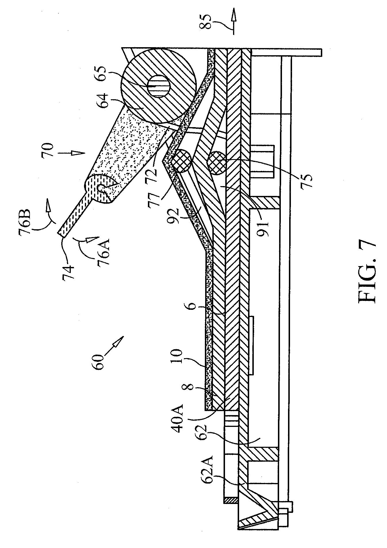
"The present invention provides a dry electroblotting system that uses a gel matrix to transfer biomolecules from a separating gel to a blotting membrane without the need for liquid buffers. This system allows for faster and more efficient electroblotting than traditional methods, with the ability to transfer in as little as 5 or 10 minutes. The system includes an electrode assembly with a body of gel matrix and an electrode that can be enclosed in a sealed package for easy use. The invention also provides pre-made, disposable electrode assemblies with additional functionality such as staining compounds, molecules for blocking non-specific binding, reducing agents, or proteases. The dry electroblotting system does not require any liquid buffers and includes a power supply that holds a transfer stack, an anode, a body of anodic gel matrix, a cathode, and a body of cathodic gel matrix. The system does not require any reservoirs for holding liquid buffers for electrophoretic transfer."

Problems solved by technology

A disadvantage of wet blotting methods is the need for relatively cumbersome apparatus and the need to prepare and handle buffers, thus making the method time consuming.
While the semi-dry electro-blotting methods known in the art solve some of the problems of wet electro-blotting methods, they still have the disadvantage of requiring preparation and handling of liquid buffer solutions for wetting the filter papers and requiring handling and alignment of the filter papers with the gel and the blotting membrane.
These methods are, therefore, still inconvenient and time consuming.
Additionally, in semi-dry electro-blotting methods, the limited amount of ions in the buffer wetted filter paper may limit the amount of current that may be used, resulting in a relatively long electro-blotting time.
Commercially available semi-dry blotters are typically limited to current densities in the range of 2-6 milliamperes per square centimeter (2-6 mA / cm2).

Method used


Image

  • Electro-Blotting Devices, Systems, and Kits, And Methods For Their Use
  • Electro-Blotting Devices, Systems, and Kits, And Methods For Their Use
  • Electro-Blotting Devices, Systems, and Kits, And Methods For Their Use

Examples


example 1

[0204] An E-PAGE 6% 96 gel (commercially available as Catalogue Number EP096-06 from Invitrogen Corporation, Carlsbad, Calif.) was run using an E-Base electrophoresis apparatus (commercially available as Catalogue Number EBM-03 from Invitrogen Corporation) for 14 min (program EP). Five microliters of E-PAGE See Blue pre-stained protein standard (commercially available as Catalogue Number LC5700 from Invitrogen Corporation, USA) were loaded in each of the wells of the E-PAGE gel cassette. After the completion of the run, the cassette was opened to remove the gel.

[0205] The gel with the resolved protein standards separated thereon was sandwiched between an anodic electrode assembly and a cathodic electrode assembly as disclosed in detail with respect to FIG. 6 hereinabove. The anodic electrode assembly included a copper mesh electrode made of a piece of braided copper mesh having a length of twelve centimeters and a width of eight centimeters cut from a Kiel copper pbn11 fabric, (com...

example 2

[0210] The electroblotting was performed as described in Example 1 above except that the electrically conducting electrode of the anodic electrode assembly was made from aluminum foil (Cat No. 1170, commercially available from 3M, USA) instead of the braided copper mesh used in the anodic electrode assembly of Example 1. The electro-blotting using such aluminum electrode resulted in somewhat less efficient blotting than the results of Example 1.

example 3

[0211] The electro-blotting was performed as described in Example 1 above except that the composition of the body of gel used in the anodic electrode assembly was as follows: a volume of gel comprising 4% agarose, 120 mM Bis Tris, 95 mM Tricine, 95 mM BES, 0.3% SDS and 20% ethylene glycol was mixed with same volume of wet fibrous cellulose phosphate based cation exchange matrix (Catalogue Number p11 commercially available from Whatman International Ltd., UK) loaded with Bis Tris ions, and the composition of the gel used to prepare the cathodic electrode assembly was as follows: a volume of gel comprising 4% agarose, 120 mM BIS TRIS, 95 mM Tricine, 95 mM BES, 0.3% SDS and 20% ethylene glycol was mixed with same volume of pre-swollen micro-granular diethylaminoethyl (DEAE) cellulose based anion exchange matrix (Catalogue Number DE52, commercially available from Whatman International Ltd., UK) loaded with Tricine ions. The blotting was carried out as detailed hereinabove for Example 1....


PUM

PropertyMeasurementUnit
current densityaaaaaaaaaa
current densitiesaaaaaaaaaa

Abstract

The invention provides a dry electroblotting system for dry blotting gels, in which the system includes an electroblotting transfer stack that comprises an analysis gel and a blotting membrane, an anode, a body of anodic gel matrix juxtaposed with the anode between the anode and the transfer stack, a cathode, and a body of cathodic gel matrix juxtaposed with the cathode between the cathode and the transfer stack, in which the anodic gel matrix and the cathodic gel matrix each comprise an ion source for electrophoretic transfer. The dry electroblotting system does not use any liquid buffers that are added to the system just before electroblotting (such as when the transfer stack is being assembled). The anode, the cathode, or both can be separate from a power supply and provided as part of a disposable electrode assembly that also includes a body of gel matrix that includes ions for electrophoretic transfer.

Description

RELATED APPLICATION [0001] This patent application is a continuation of U.S. application Ser. No. 11 / 357,416, filed on 21 Feb. 2006, which claims the benefit of priority of U.S. Provisional Patent Application No. 60 / 655,420 filed on 24 Feb. 2005, entitled “Disposable Dry Electro-blotting Electrodes, Methods for their Use and Dry Blotting,” and U.S. Provisional Patent Application No. 60 / 774,231 filed on 17 Feb. 2006, entitled “Dry Electro-blotting Devices, Systems, and Kits, and Methods for their Use” naming Ilana Margalit, Uri Yogev, Sela Itay, Yuri Katz, Adam Sartiel, and Tim Updyke as inventors. The content and subject matter of these patent applications are hereby incorporated by reference in their entireties, including all text and drawings.FIELD OF THE INVENTION [0002] The present invention relates generally to the field of gel blotting and more specifically to dry electroblotting compositions and methods. BACKGROUND [0003] The separation of molecular species using gel electrop...

Claims


Application Information

Patent Timeline
Patent Type & Authority Applications(United States)
IPC IPC(8): B01D61/42G01N27/00
CPCG01N27/44739
Inventor MARGALIT, ILANAYOGEV, URISELA, ITAYKATZ, YURISARTIEL, ADAM
Owner LIFE TECH ISRAEL
Learn More