Eureka AIR delivers breakthrough ideas for toughest innovation challenges, trusted by R&D personnel around the world.

Microstructured optical device for polarization and wavelength filtering

Inactive Publication Date: 2006-11-23
HOBBS DOUGLAS S
View PDF7 Cites 114 Cited by
  • Summary
  • Abstract
  • Description
  • Claims
  • Application Information

AI Technical Summary

Benefits of technology

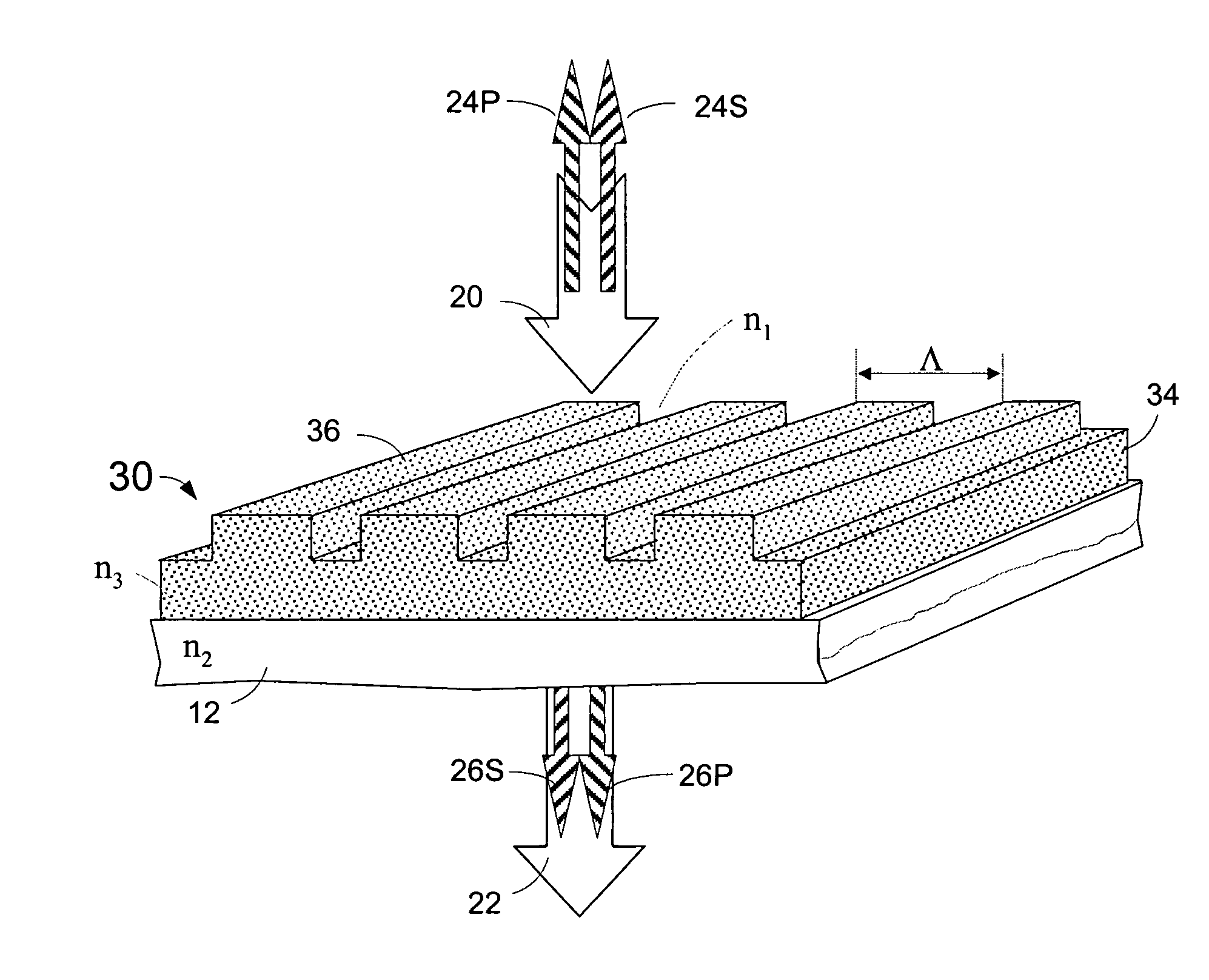
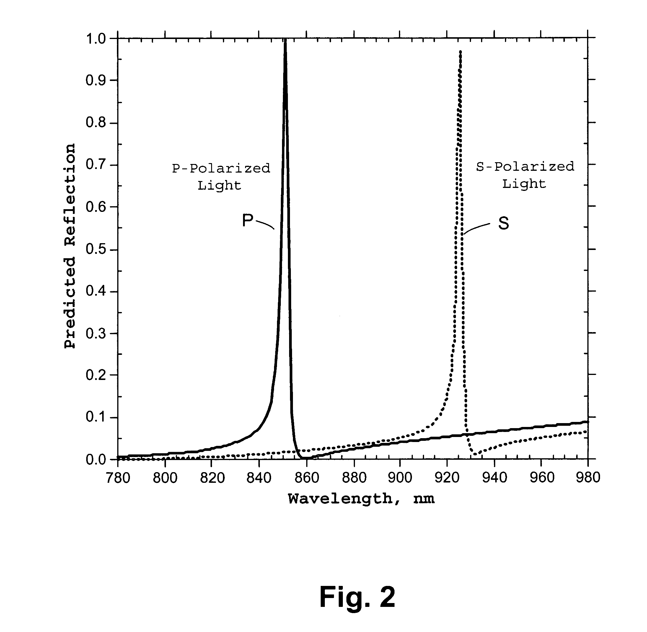
[0016] In the following specification, polarizing surface structure waveguide filters are disclosed. The filters serve to transmit a specific polarization state for a given range of wavelengths while reflecting the orthogonal polarization state. This effect is created by a surface structure waveguide that is composed of asymmetric features such as an array of lines. The features of the structural waveguide will resonate with one wavelength of light that is polarized parallel to the grating lines, and with another wavelength of light that is polarized in a direction perpendicular to the grating lines. The same effect would be produced with a two-dimensional array of structures where the individual features are asymmetric such as rectangles, or where the structure spacing of the array is different in one direction than the structure spacing in the orthogonal direction. When the illuminating source contains a narrow range of wavelengths as with laser or light emitting diode (LED) light sources, a polarizing surface structure waveguide filter can be configured to transmit or reflect polarized light that matches the laser or LED wavelength. The same filter illuminated by a randomly polarized broad-band light source will reflect or transmit two narrow-band spectral regions that are polarized with orthogonal states. By designing an asymmetric surface structure waveguide filter that operates on multiple wavelength bands simultaneously, a polarizing multi-band filter can be realized that is capable of polarizing the discrete spectral content of the typical fluorescent lamp and LED light sources used to illuminate liquid crystal displays. This inventive device combines the benefits of simple inexpensive manufacturing found with surface relief microstructure optical retarders and waveguide resonant filters, with the low-loss large-area polarizing function found with stretched dielectric film stacks.
[0018] A large application for a non-absorbing broad band microstructured reflective polarizer is found in the back lights used to illuminate LCDs. As described above LCDs employ absorptive polarizers that selectively absorb all light of one polarization state. A non-absorbing reflective polarizer based on microstructures would provide a significant increase in LCD brightness by replacing the absorbing polarizers with an efficient polarizer that reflected the unwanted polarization state back into the light source where it would undergo polarization conversion and be recycled as transmitted light. The microstructures would allow the low cost high-volume manufacturing of such a polarizing film that could effectively compete in the one billion dollar reflective polarizer market currently enjoyed exclusively by the 3M company with their DBEF product.
[0019] One aspect of the present invention involves a guided-mode resonance surface structure optical filter that simultaneously filters and polarizes a narrow-range of light wavelengths contained within a broad-band light source. The surface structure polarizing filter provides high efficiency, reflecting or transmitting polarized light without loss due to absorption as found in conventional polarizing devices and color filters. Low cost manufacturing is also afforded through replication of the surface relief structures comprising the polarizing filter.
[0021] Another aspect of the present invention is directed towards a polarizing optical filter having one or more guided-mode surface structures to reflect or transmit polarized light in one or more discrete bands of light wavelengths from a broad spectrum of incident light. The surface structures are arranged, or stacked, such that the illuminating broad-band light encounters each filter in series as it propagates. Each filter in the stack is designed to polarize and reflect or transmit a narrow-band of wavelengths that matches a spectral component of the illuminating source. Each filter in the stack covers an area at least as large as the illuminating light source. For example, three polarizing surface structure filters that polarize and reflect or transmit red (R), green (G), and blue light (B) respectively, could be layered to form an RGB color filter sheet where the RGB filters are set to match the spectral content of the light sources used in most liquid crystal displays. Such a polarizing filter sheet would be a low-cost competitor to the 3M reflective polarizer film described above.
[0024] In another application, a reflective polarizing surface structure optical filter could be used as a laser cavity mirror, or a transmissive filter could be built onto the facets of the lasing medium. Both filters would offer the particular advantage of high transmission of the pump light illumination combined with narrow-band reflection of the laser light. In addition, the filters can be constructed from the lasing medium itself to reduce thermal lensing problems and the thermal damage typically found with multiple-layer thin-film filters used with high power lasers.
[0026] In still another application, polarizing surface structure filters can be provided to enhance the signal discrimination in a laser communications system. Amplitude modulated information could be encoded on one or more polarization states of a laser light source. For example, a free-space laser communication system between Earth and Mars could employ polarized light and polarizing narrow-band filters to support communication for an extended time as the orbit of Mars relative to the Earth causes an increase in background light from the Sun.

Problems solved by technology

The amount of light transmitted through the liquid crystal pixels is limited by the absorption in both the color filtering dyes and the polarizing sheets.
This poor light transmission limited the market acceptance of LCDs for many years.
The reflective polarizing film produced by 3M is highly complex and expensive.
Wire-grid polarizers are commonly used for polarizing infrared light, but have not been accepted for use with visible light because of the absorption loss from the metal lines and the requirement of producing extremely small grating line widths—typically on the order of 60 to 75 nanometer (nm)—patterned over areas which can be large such as in the display application.
Waves traveling radially outward in the plane will interfere with waves reflected from the structures allowing the confined beam to leak out of the plane, propagating in a direction opposite the incident direction.

Method used


Image

  • Microstructured optical device for polarization and wavelength filtering
  • Microstructured optical device for polarization and wavelength filtering
  • Microstructured optical device for polarization and wavelength filtering

Examples


Embodiment Construction

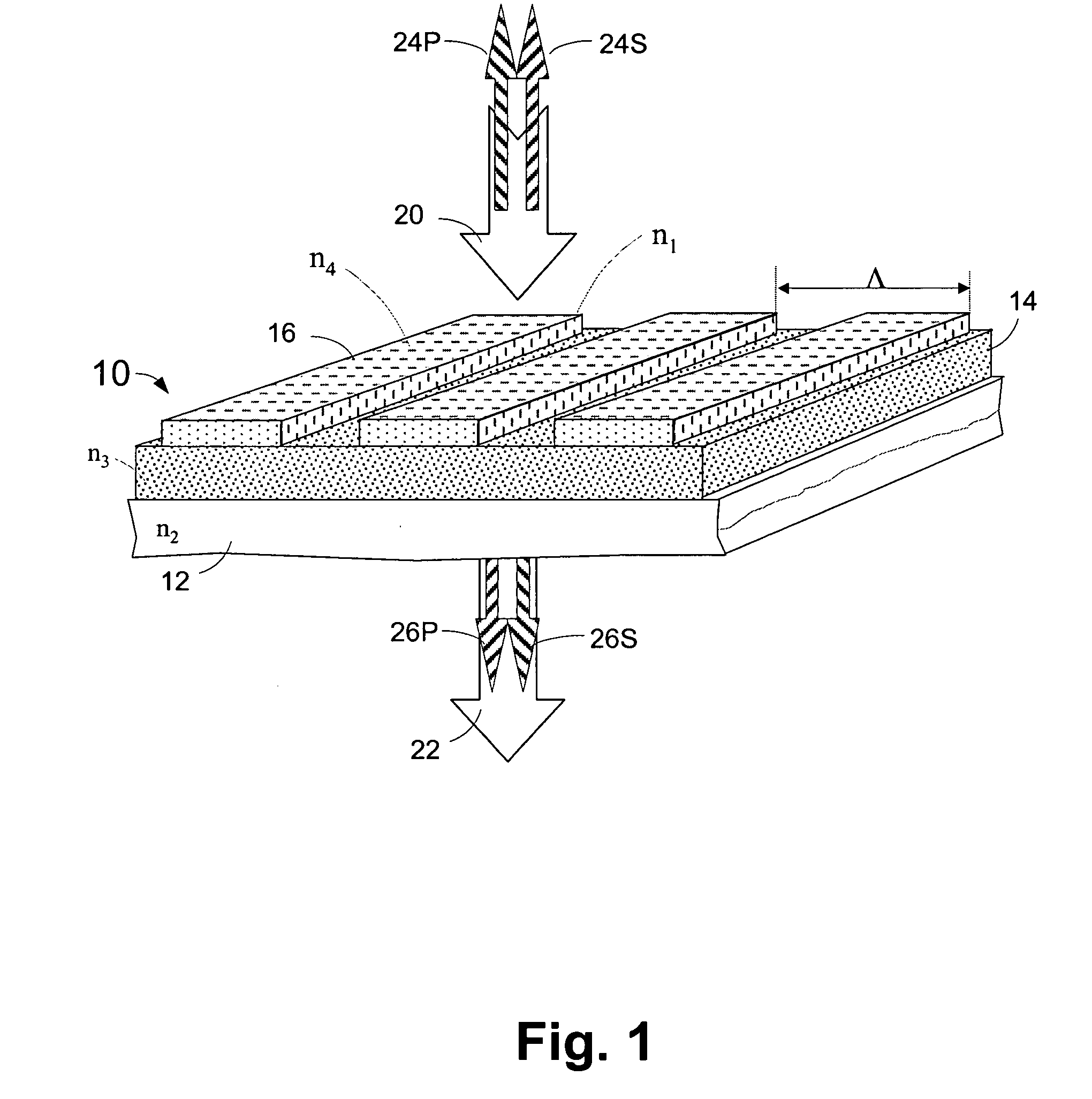
[0071]FIG. 1 shows a perspective view with cross section of a surface structure polarizing optical filter 10 capable of reflecting light of a particular range of wavelengths and a particular electric field orientation 24P and 24S, or polarization state, out of a broad spectrum, randomly polarized light beam 20 striking the device at normal incidence. Transmitted light beam 22 contains the same randomly polarized broad spectrum light as incident beam 20 except for wavelengths 26P and 26S that propagate with an electric field orientation orthogonal to reflected light 24P and 24S. Note that the use of the identifiers ‘S’ and ‘P’ refer to orthogonal electric field orientations in all that follows, with S meaning an electric field vibrating parallel to the long dimension of the surface structures, and P designating an electric field vibrating in the orthogonal direction, or perpendicular to the long dimension of the surface structures.

[0072] The polarizing surface structure optical filt...


PUM


Abstract

A microstructure-based polarizer is described. The device acts as an electromagnetic wave filter in the optical region of the spectrum, filtering multiple wavelength bands and polarization states. The apparatus comprises a substrate having a surface relief structure containing dielectric bodies with physical dimensions smaller than the wavelength of the filtered electromagnetic waves, such structures repeated in an array covering at least a portion of the surface of the substrate. The disclosed structure is particularly useful as a reflective polarizer in a liquid crystal display, or as polarizing color filter elements at each pixel in a display. Other applications such as polarization encoded security labels, polarized room lighting, and color filter arrays for electronic imaging systems are made practical by the device.

Description

CROSS REFERENCE TO RELATED APPLICATION [0001] This application claims priority of Provisional Application Ser. No. 60 / 682,049, filed on May 18, 2005 entitled “MICROSTRUCTURED OPTICAL DEVICE FOR POLARIZATION AND WAVELENGTH FILTERING”.FIELD OF THE INVENTION [0002] This invention relates to an optical device that filters wavelengths of light, and filters the light polarization. Wavelength and polarization filters are common optical elements in displays, room lighting, video and still imaging cameras, and security labels and tags. The invention will find particular use as a polarizing element for laser and LED light sources used in communication and security systems, and most significantly, as inexpensive, high-efficiency polarizing filters for liquid crystal display backlights or color filter arrays. BACKGROUND OF THE INVENTION [0003] Thin, flat, information and video displays based on liquid crystal technology are used exclusively in portable computers and hand-held devices such as mo...

Claims


Application Information

Patent Timeline
IPC IPC(8): G02F1/1335
CPCG02B5/1809G02B5/201G02B5/203G02F2201/307G02F1/133533G02F1/133536G02F2001/133538G02B5/3058B42D25/324B42D25/328G02F1/133538G02F1/1335
Inventor HOBBS, DOUGLAS S.
Owner HOBBS DOUGLAS S
Why Eureka
Eureka Blog
Learn More