Eureka AIR delivers breakthrough ideas for toughest innovation challenges, trusted by R&D personnel around the world.

Modular heat exchanger having a brazed core and method for forming

a heat exchanger and module technology, applied in the direction of stationary conduit assemblies, lighting and heating apparatus, applications, etc., can solve the problems of large drying oven and furnace, large construction cost, and inadequate heat exchangers for more physically demanding applications, so as to reduce equipment downtime and reduce construction costs. , the effect of flexural strength

Inactive Publication Date: 2006-09-07
LESAGE PHILIP GEORGE
View PDF7 Cites 36 Cited by
  • Summary
  • Abstract
  • Description
  • Claims
  • Application Information

AI Technical Summary

Benefits of technology

The present invention provides an improved modular heat exchanger that is composed of brazed cores, which have greater heat transfer efficiency than prior art modular heat exchangers with mechanically-joined tubes and fins. The invention also includes several methods for manufacturing the brazed core that prevent distortion during the brazing process and allow for easy assembly of the core with a manifold or tank assembly. The brazed core construction allows for a smaller drying oven and brazing furnace, and the resulting heat exchanger is more durable and reliable for heavy-duty applications. The invention also includes resilient grommets that form a flexible joint between the tubes and header, which prevents leaks and damage to the heat exchanger. Overall, the invention provides a modular heat exchanger that is more efficient, durable, and easy to assemble.

Problems solved by technology

One drawback is that the monolithic brazed construction requires a large drying oven and furnace, both of which are expensive to purchase and operate.
Another drawback is that the brazed construction renders such heat exchangers inadequate for more physically demanding applications, such as in the truck and heavy-duty equipment industries.
More specifically, monolithic brazed heat exchangers are rigid and therefore do not readily “give” during pressure and thermal cycles, when subject to vibration, or when otherwise distorted by their operating environment.
As a result, if a monolithic brazed heat exchanger is used in these applications, cracks eventually develop in the tube-to-header joint where the tubes are brazed to the manifold.
Repair of cracks in the tube-to-header joint is expensive, and this mode of failure constitutes a major source of scrappage in the heat exchanger industry.
Finally, the working environment of a heavy-duty vehicle employed in construction is severe, leading to a high incidence of damage to the tubes and fins from impacts by debris.
However, prior art modular constructions have been generally unable to adopt the brazed tube-and-center core design described previously, in which the tubes and / or fins are formed from a clad aluminum alloy.
As a result, assembling a header or tank to the brazed core is impossible because the tubes are misaligned with apertures formed in the header or tank to receive the tubes.
While such an approach may solve the misalignment problem noted above, the result is a module that is nearly as expensive to manufacture as a conventional monolithic brazed heat exchanger.
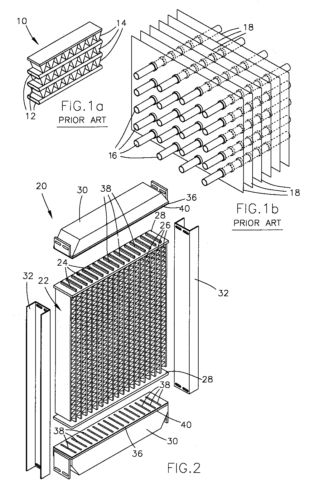
Unfortunately, mechanical joining methods do not yield a metal-to-metal joint that conducts heat as well as the brazed joints formed with the brazed core design illustrated in FIG. 1a.
As a result, heat transfer between the fluid in the tubes 16 and air flowing over the fins 18 is not as efficient in prior art modular constructions as compared to monolithic brazed constructions.
From the above, it is apparent that the prior art is lacking an economical modular heat exchanger design that incorporates a brazed core assembly, and further lacks a method or process by which such a heat exchanger could be manufactured.

Method used


Image

  • Modular heat exchanger having a brazed core and method for forming
  • Modular heat exchanger having a brazed core and method for forming
  • Modular heat exchanger having a brazed core and method for forming

Examples


Embodiment Construction

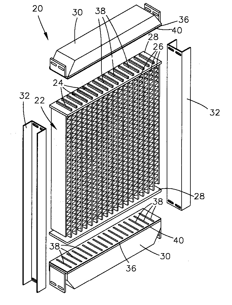
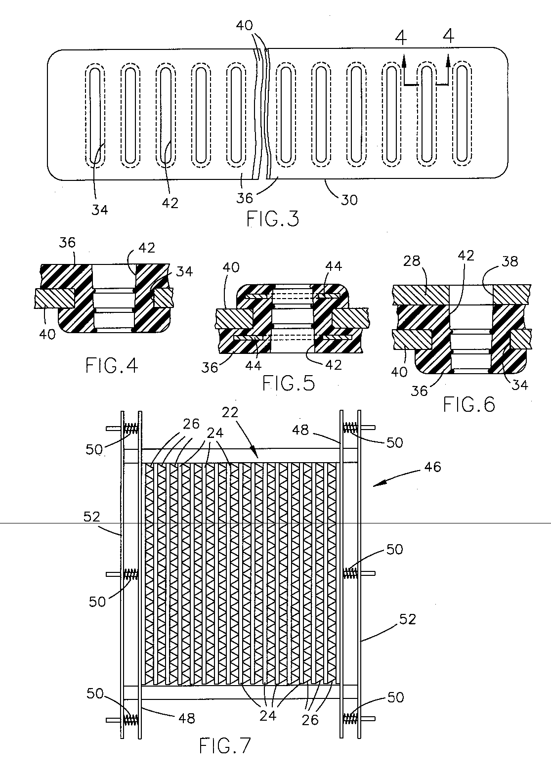
[0029] An improved modular heat exchanger is provided that is suitable for automotive applications, and particularly radiators for heavy duty equipment. FIG. 2 represents a heat exchanger 20 that incorporates the teachings of this invention, and includes a brazed core assembly 22 preferably composed of flat-type cooling tubes 24 and sinusoidal centers 26. The inclusion of a brazed core assembly 22 in the heat exchanger 20 of this invention represents a significant improvement over prior art modular heat exchangers because of enhanced heat transfer efficiencies associated with the use of flat tubes 24, sinusoidal centers 26, and a tube-to-center braze joint. While prior art modular heat exchangers have often required the use of mechanically-joined round tubes and fins in order to maintain positional tolerances for the tubes, the brazed core assembly 22 of this invention is brazed in a manner that avoids core shrinkage and therefore maintains the required positional tolerances for mat...


PUM

PropertyMeasurementUnit
thicknessaaaaaaaaaa
thicknessaaaaaaaaaa
heightaaaaaaaaaa

Abstract

A modular heat exchanger suitable for automotive applications, and methods for forming the modular heat exchanger. The modular heat exchanger construction incorporates a monolithic brazed core assembly composed of flat-type cooling tubes and sinusoidal centers. The required positional tolerances of the tubes for mating with the remainder of the heat exchanger are maintained within the brazed core assembly by minimizing core shrinkage resulting from the brazing operation during which the tubes are brazed to the centers.

Description

CROSS REFERENCE TO RELATED APPLICATIONS [0001] This is a division patent application of co-pending U.S. patent application Ser. No. 08 / 489,795, filed Jun. 13, 1995, whose contents are incorporated herein by reference.BACKGROUND OF THE INVENTION [0002] The present invention relates to an improved modular heat exchanger of the type used in the automotive industry. More particularly, this invention relates to a modular heat exchanger having a brazed core assembly and techniques by which such a heat exchanger is assembled, in which the brazed core is manufactured such that the spacial positions of its cooling tubes after brazing enable the tubes to properly mate with elastomerically-sealed apertures formed in the heat exchanger's headers, and thereby form a modular heat exchanger whose brazed core can be readily removed for repair or replacement, and whose overall construction is capable of withstanding structural distortions without leaks and structural failures occurring between the t...

Claims


Application Information

Patent Timeline
Patent Type & Authority Applications(United States)
IPC IPC(8): B21D53/02B21D53/00F28D1/053F28F9/02F28F9/14F28F9/16F28F9/18
CPCB21D53/085Y10T29/49359B23K2201/14F28D1/05366F28D1/05383F28D2001/0266F28D2021/0094F28F9/0229F28F9/14F28F9/165F28F9/18F28F9/262F28F2275/04F28F2255/02F28F2225/08F28F2265/26F28F2230/00Y10T29/49373Y10T29/49389Y10T29/49377Y10T29/49393Y10T29/4935Y10T29/49375B23K1/0012B23K2101/14
Inventor LESAGE, PHILIP GEORGE
Owner LESAGE PHILIP GEORGE
Why Eureka
Eureka Blog
Learn More