Method of forming a thermoactive binder composite

a thermoactive binder and composite material technology, applied in the field of thermoactive binder composite material forming, can solve the problems of slow composite board production, small reduction of press time, and dramatic increase in press time, so as to facilitate proper wetting of filler particles, increase bonding, and increase the effect of final product strength

Inactive Publication Date: 2006-05-18
ENGINEERED COMPOSITES
View PDF99 Cites 7 Cited by
  • Summary
  • Abstract
  • Description
  • Claims
  • Application Information

AI Technical Summary

Benefits of technology

[0043] It is important to obtain thorough mixing of the thermoactive binder and filler. If discrete thermoactive binder pieces and filler particles are used, they should preferably be of generally the same size and weight. This helps to achieve adequate inter-suspension of pieces and particles in the mixture and facilitates proper wetting of the filler particles. If a liquid thermoset resin is used as the thermoactive binder, it may be sprayed over the filler to accomplish the same result. Similarly, powdered thermoactive binders may be applied to the filler particles to create the desired disper...

Problems solved by technology

The time spent in pressing/heating the binder to soften and ultimately cure it slows the production of composite boards, and, to a large extent, that time is dependent on the mechanism of heat transfer used to supply heat to the mat.
Because of the poor thermal conductivity of the cellulose and thermoset polymer constituents, this method requires that the mat remain in the press for a substantial amount of time to allow the core temperature of the mat to be raised to a level sufficient to cure the thermoset polymer binder and complete panel formation.
This is particularly a problem with thick mats because press time increases dramatically with increasing mat thickness.
However, only slight reductions in press time were achieved, and increased platen temperature scorched or otherwise damaged the panels.
However, such steam proposals suffer from drawbacks as well because more press time is required to rid the mat of excess moisture.
Also, the surface of the panel often blisters due to the steam heat.
This technology, however, has serious limitations.
First, tolerances in the screw extruder permit only sawdust sized cellulose particles to be used.
This drastically reduces the strength and stiffness of the material, since fiber length and orientation contribute substantially to the mechanical properties of a composite material.
This method is also limited to a mix of about 50/50 thermoplastic-to-cellulose because of the melt/flow restrictions of the extruder.
Greater tha...

Method used


Image

  • Method of forming a thermoactive binder composite
  • Method of forming a thermoactive binder composite
  • Method of forming a thermoactive binder composite

Examples


Embodiment Construction

Platen

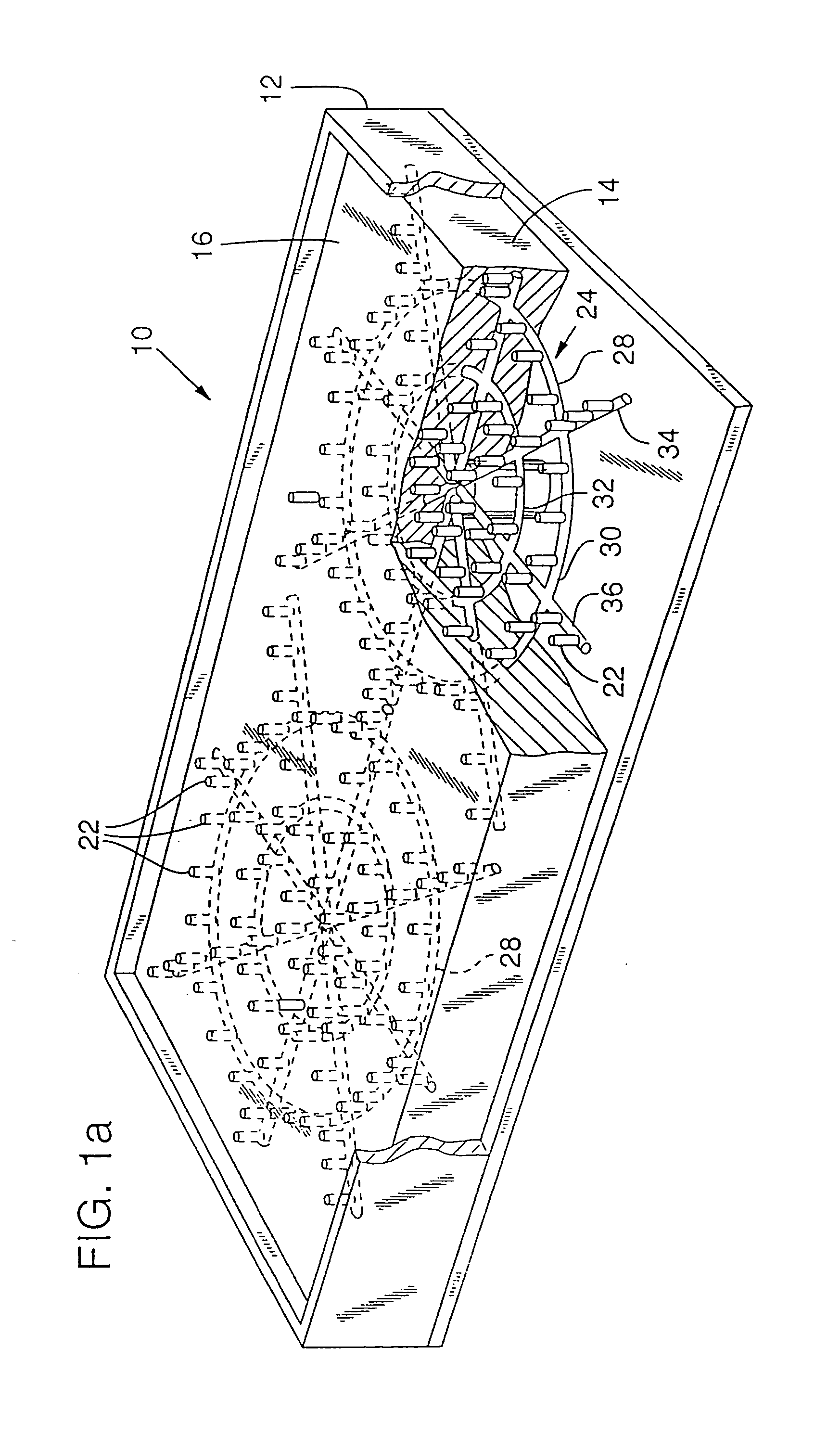
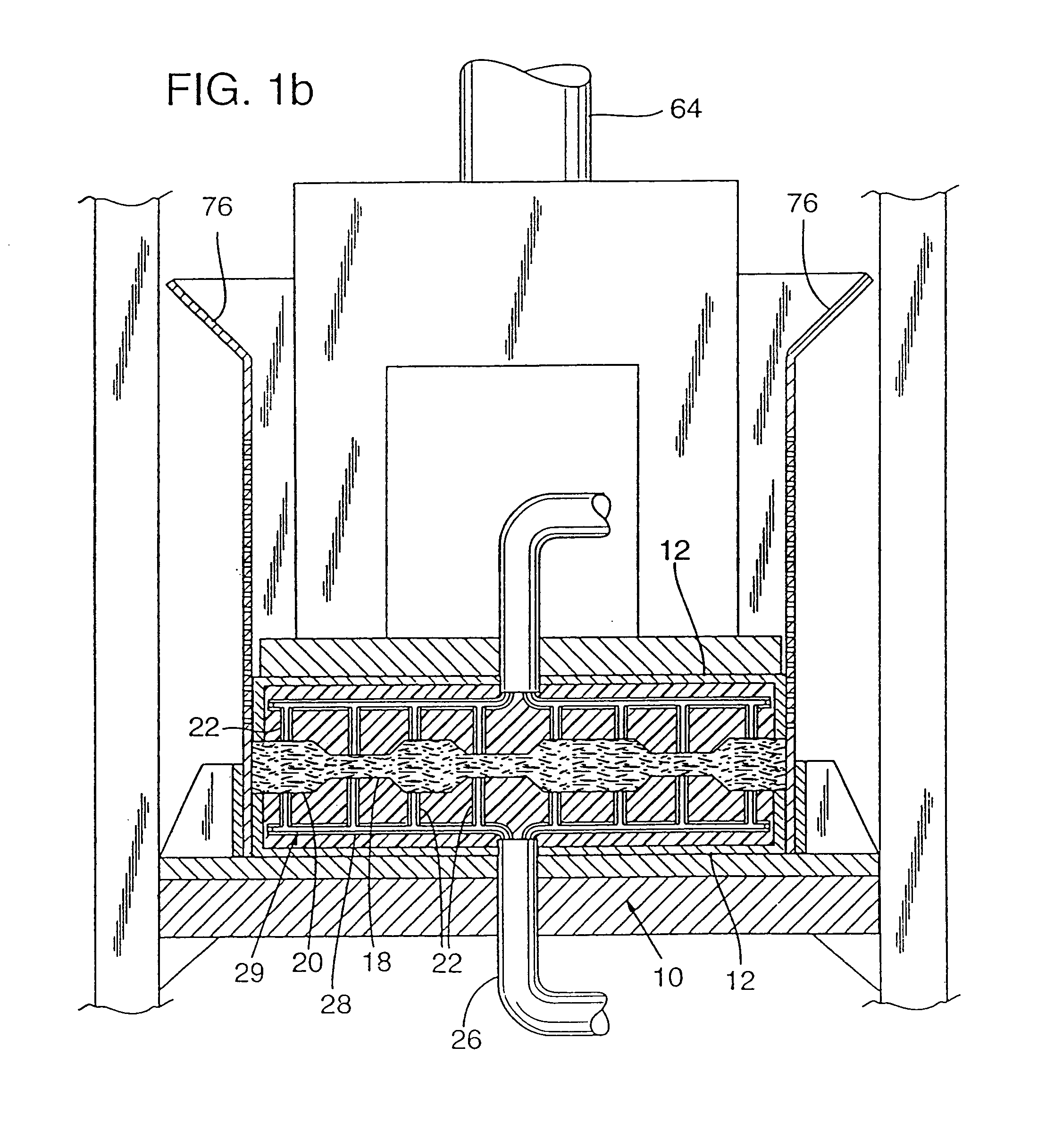
[0072] A platen 10 made according to the preferred embodiment of the present invention is shown in FIG. 1a. Platen 10 is designed to compress and deliver heat to a press charge in a press. Platen 10 includes a support frame 12 which holds a die 14. One surface of die 14 forms an inner face 16 for contacting the press charge. Inner face 16 may be made flat or formed with protrusions 18 and / or depressions 20 to shape the product being pressed as shown in FIG. 1b. Die 14 is formed of high temperature (600° F.) RTV rubber, such as Dow Chemical 3120 RTV Rubber, by casting. Protrusions 18 and depressions 20 are incorporated into die 14 directly during the casting process.

[0073] Platen 10 further includes a plurality of air jets 22 disposed in die 14 and opening onto inner face 16. Air jets 22 provide the injection points where the hot air is injected into the press charge. An air distribution manifold 24 is cast into die 14 and disseminates the hot air from two intake tubes 26 to ...


PUM

PropertyMeasurementUnit
Temperatureaaaaaaaaaa
Lengthaaaaaaaaaa

Abstract

A method of forming a thermoactive binder composite product is performed by injecting a hot dry gas to activate the thermoactive binder. In the preferred embodiment, the hot dry gas is air. The method is particularly beneficial as applied to forming thermoplastic composite products and particularly thermoplastic/cellulose composites. Also part of the present invention is a two stage pressing process in which hot gas is injected during the first stage and the press charge is precompressed. The press charge is then placed in a second consolidation press where the hot gas is no longer injected and it is consolidated and cooled. Machinery for practicing the method includes a platen with a platen press which includes upper and lower platens with a plurality of hot air injection jets disposed on the surface of each platen. The platens are spaced apart and surrounded on the sides by an air-permeable containment shell structure to form a compression chamber to hold the base material to be pressed. Other machinery includes a consolidation press.

Description

CROSS REFERENCE TO RELATED APPLICATIONS [0001] This application is a continuation of U.S. patent application Ser. No. 09 / 990,472, filed Nov. 20, 2001 which is a continuation of U.S. patent application Ser. No. 09 / 109,465, filed Jul. 2, 1998, which is a continuation of U.S. patent application Ser. No. 08 / 487,285, filed Jun. 7, 1995, which is a continuation-in-part of U.S. patent application Ser. No. 08 / 468,512, filed Jun. 5, 1995, which is a continuation of U.S. patent application Ser. No. 08 / 131,204, filed Oct. 1, 1993, which is a continuation-in-part of U.S. patent application Ser. No. 07 / 959,228, filed Oct. 9, 1992, now U.S. Pat. No. 5,356,278, issued Oct. 18, 1994, which is a continuation-in-part of U.S. patent application Ser. No. 07 / 677,416, filed Mar. 29, 1991, now U.S. Pat. No. 5,155,146, issued Oct. 13, 1992, each of which is hereby incorporated by reference.BACKGROUND [0002] The present invention relates to a novel method and structure for forming composite products using t...

Claims


Application Information

Patent Timeline
IPC IPC(8): B29C43/02B27N3/00B27N3/08B29C35/04B29C43/00B29C48/07B29C70/08B29C70/46B29C70/56C08J11/06D04H1/58D04H1/64
CPCB27N3/00B27N3/086B29C31/08B29C35/045B29C43/003B29C43/52B29C47/0019B29C47/54B29C70/081B29C70/46B29C70/56B29K2105/04B29K2105/0809B29K2105/12B29K2105/26B29K2311/14B29L2031/772C08J11/06C08J2325/06D04H1/58D04H1/642D04H1/62D04H1/66B29C48/07Y02W30/62
Inventor REETZ, WILLIAM R.TAYLOR, RONALD R.
Owner ENGINEERED COMPOSITES
Why Eureka
Try Eureka