Projection optical system, exposure apparatus, and exposure method

a technology of projection optical system and exposure apparatus, which is applied in the direction of microlithography exposure apparatus, printers, instruments, etc., can solve the problems of inability to secure a large effective image-side numerical aperture, inability to accurately correct, and increased reflection loss on optical surfaces

Inactive Publication Date: 2006-04-27
NIKON CORP
View PDF15 Cites 13 Cited by
  • Summary
  • Abstract
  • Description
  • Claims
  • Application Information

AI Technical Summary

Benefits of technology

[0024] wherein the projection optical system has a still exposure region substantially smaller than one shot-area to be formed on the photosensitive substrate, and
[0025] wherein the projection optical system repeats a projection exposure in a portion of the shot-area more than once in the projection exposure in the shot-area.

Problems solved by technology

In this case, if the maximum incidence angle θ is increased in order to increase the image-side numerical aperture, it will result in increasing the incidence angle to the photosensitive substrate and the emergence angle from the projection optical system, and therefore increasing reflection loss on optical surfaces.
Thus it will fail to secure a large effective image-side numerical aperture.
In the dioptric projection optical systems, it will result in failing to well correct for off-axis aberrations such as coma and, in turn, failing to secure a large still exposure region (effective exposure region: effective imaging area) and to avoid an increase in the size of lenses.
However, if the projection magnification of the projection optical system is set smaller than normal, it will result in increasing the mask-side illumination area optically corresponding to a shot-area having a required size, and thus failing to cover this large illumination area by a currently predominating 6-inch reticle.
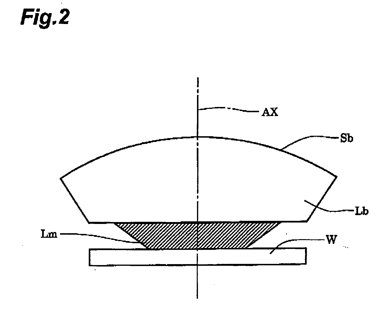
However, if a configuration wherein a medium is filled in the optical path between the projection optical system and the photosensitive substrate is adopted in order to achieve the large image-side numerical aperture, quick scanning exposure is impossible, for example, because of the intervention of the liquid-like medium, and it could cause a drop of throughput.

Method used


Image

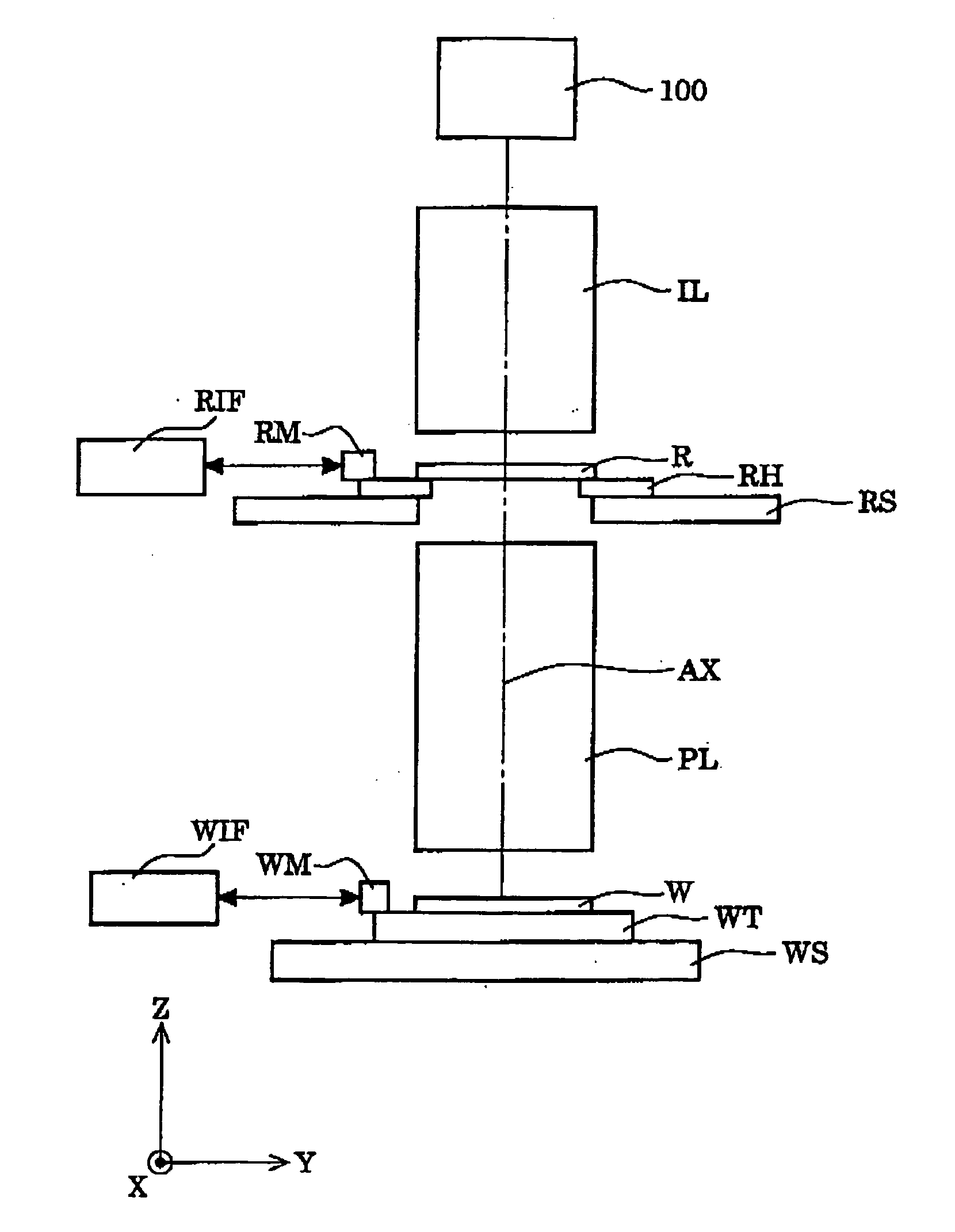
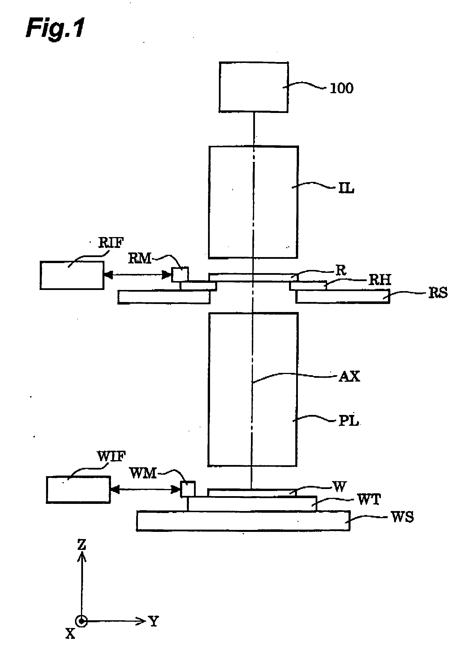
  • Projection optical system, exposure apparatus, and exposure method
  • Projection optical system, exposure apparatus, and exposure method
  • Projection optical system, exposure apparatus, and exposure method

Examples


first example

[0099]FIG. 3 is an illustration showing a lens configuration of a projection optical system according to the first example of the present embodiment. With reference to FIG. 3, the projection optical system PL of the first example is composed of the following components arranged in order from the reticle side: a biconcave lens L1 whose concave surface of aspherical shape is kept toward the wafer; a negative meniscus lens L2 whose concave surface is kept toward the reticle; a positive meniscus lens L3 whose concave surface of aspherical shape is kept toward the reticle; a biconvex lens L4; a biconvex lens L5 whose convex surface of aspherical shape is kept toward the reticle; a positive meniscus lens L6 whose convex surface of aspherical shape is kept toward the reticle; a positive meniscus lens L7 whose concave surface of aspherical shape is kept toward the wafer; a negative meniscus lens L8 whose convex surface is kept toward the reticle; a biconcave lens L9 whose concave surface of...

second example

[0106]FIG. 6 is an illustration showing a lens configuration of a projection optical system according to the second example of the present embodiment. With reference to FIG. 6, the projection optical system PL of the second example is composed of the following components arranged in order from the reticle side: a biconcave lens L1 whose concave surface of aspherical shape is kept toward the wafer, a negative meniscus lens L2 whose concave surface is kept toward the reticle; a negative meniscus lens L3 whose concave surface of aspherical shape is kept toward the reticle; a positive meniscus lens L4 whose concave surface is kept toward the reticle; a biconvex lens L5; a biconvex lens L6; a positive meniscus lens L7 whose convex surface is kept toward the reticle; a negative meniscus lens L8 whose convex surface is kept toward the reticle; a biconcave lens L9; a biconcave lens L10 whose concave surface of aspherical shape is kept toward the reticle; a negative meniscus lens L11 whose c...

third example

[0112]FIG. 9 is an illustration showing a lens configuration of a projection optical system according to the third example of the present embodiment. With reference to FIG. 9, the projection optical system PL of the third example is composed of the following components arranged in order from the reticle side: a biconcave lens L1 whose concave surface of aspherical shape is kept toward the wafer; a negative meniscus lens L2 whose concave surface is kept toward the reticle; a positive meniscus lens L3 whose concave surface of aspherical shape is kept toward the reticle; a positive meniscus lens L4 whose concave surface is kept toward the reticle; a biconvex lens L5; a positive meniscus lens L6 whose convex surface is kept toward the reticle; a positive meniscus lens L7 whose convex surface is kept toward the reticle; a positive meniscus lens L8 whose convex surface is kept toward the reticle; a negative meniscus lens L9 whose convex surface is kept toward the reticle; a biconcave lens...


PUM

PropertyMeasurementUnit
refractive indexaaaaaaaaaa
sizeaaaaaaaaaa

Abstract

An exposure apparatus uses a dioptric projection optical system easy to manufacture and a mask of an ordinary size, and is able to effect a projection exposure in a high resolution with high throughput, while securing a large effective image-side numerical aperture through the intervention of a high-refractive-index medium in an optical path between the projection optical system and a photosensitive substrate. The exposure apparatus is configured to effect a projection exposure of a reduced image of a pattern formed on the mask (R), through the projection optical system (PL) onto the photosensitive substrate (W). Where a refractive index of an atmosphere in an optical path of the projection optical system is 1, the optical path between the projection optical system and the photosensitive substrate is filled with a medium having the refractive index larger than 1.1. The projection optical system has still exposure regions substantially smaller than one shot-area to be formed on the photosensitive substrate, and repeats a projection exposure in a portion of the shot-area more than once in the projection exposure in the shot-area.

Description

RELATE APPLICATIONS [0001] This is a Continuation-In-Part application of International Patent application serial No. PCT / JP2004 / 005957 filed on Apr. 23, 2004, now pending.BACKGROUND OF THE INVENTION [0002] 1. Field of the Invention [0003] The present invention relates to a projection optical system, exposure apparatus, and exposure method and, more particularly, to a high-resolution projection optical system suitable for exposure apparatus used in production of semiconductor devices, liquid-crystal display devices, etc. by photolithography. [0004] 2. Related Background Art [0005] The photolithography for production of the semiconductor devices and others is implemented using a projection exposure apparatus for projecting a pattern image of a mask (or a reticle) through a projection optical system onto a wafer (or a glass plate or the like) coated with a photoresist or the like. The resolving power (resolution) required for the projection optical system of the projection exposure app...

Claims


Application Information

Patent Timeline
Patent Type & Authority Applications(United States)
IPC IPC(8): G03B27/42G03F7/20
CPCG03F7/70241G03F7/70341G03F7/70875G03F7/70466G03F7/70425
Inventor OMURA, YASUHIROIKEZAWA, HIRONORIISHIDA, KUMIKO
Owner NIKON CORP
Why Eureka
Try Eureka