Reader/writer
a technology of reader/writer and contactless tag, which is applied in the direction of burglar alarm mechanical actuation, burglar alarm by hand-portable article removal, instruments, etc., can solve the problem that the transmission power provided to the selected antenna coil in the reader/writer is not sufficiently transmitted to the antenna coil in the contactless tag, and cannot be efficiently communicated with the contactless tag located away from the reader/writer. the effect of efficient transmission of transmission power
- Summary
- Abstract
- Description
- Claims
- Application Information
AI Technical Summary
Benefits of technology
Problems solved by technology
Method used
Image
Examples
first embodiment
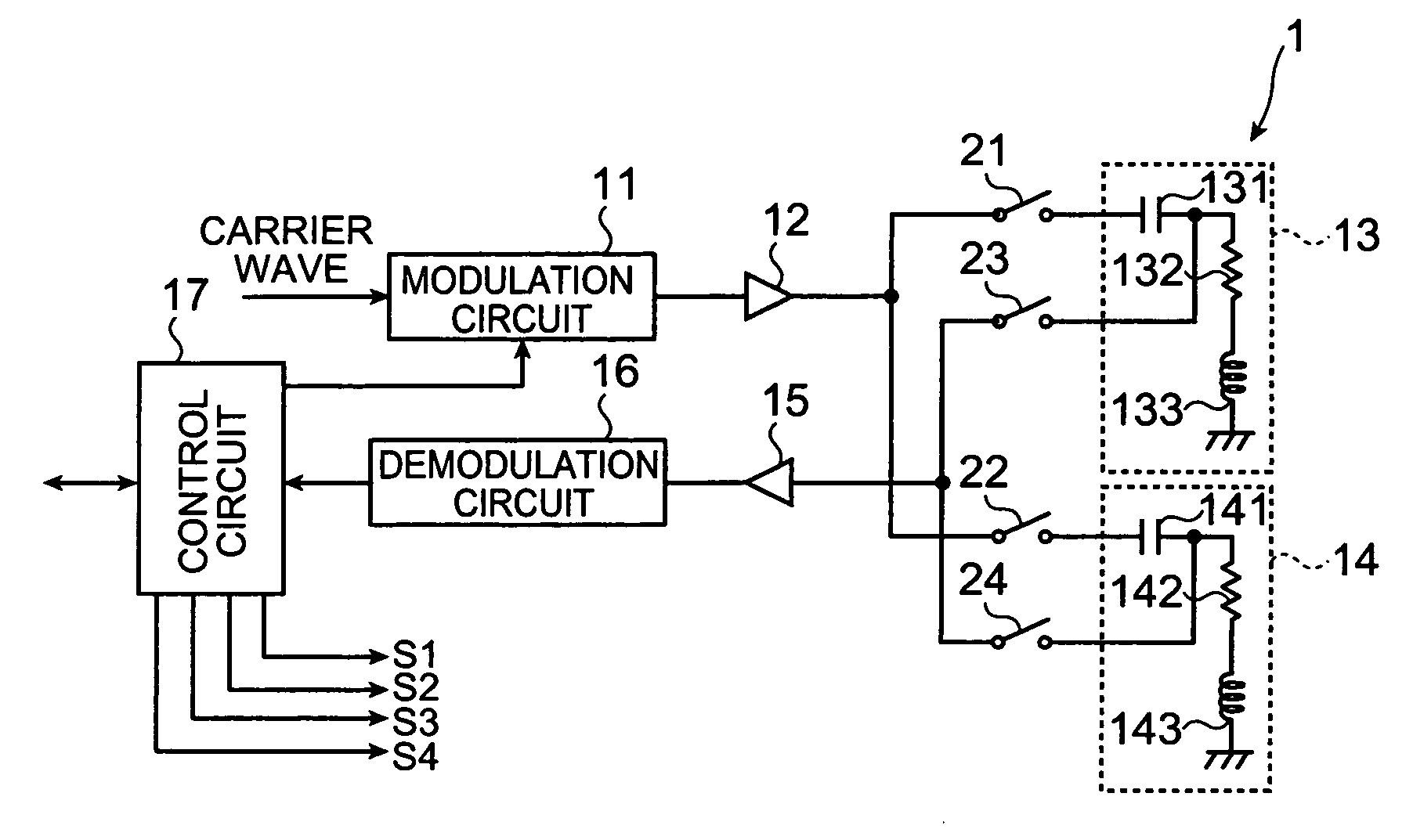
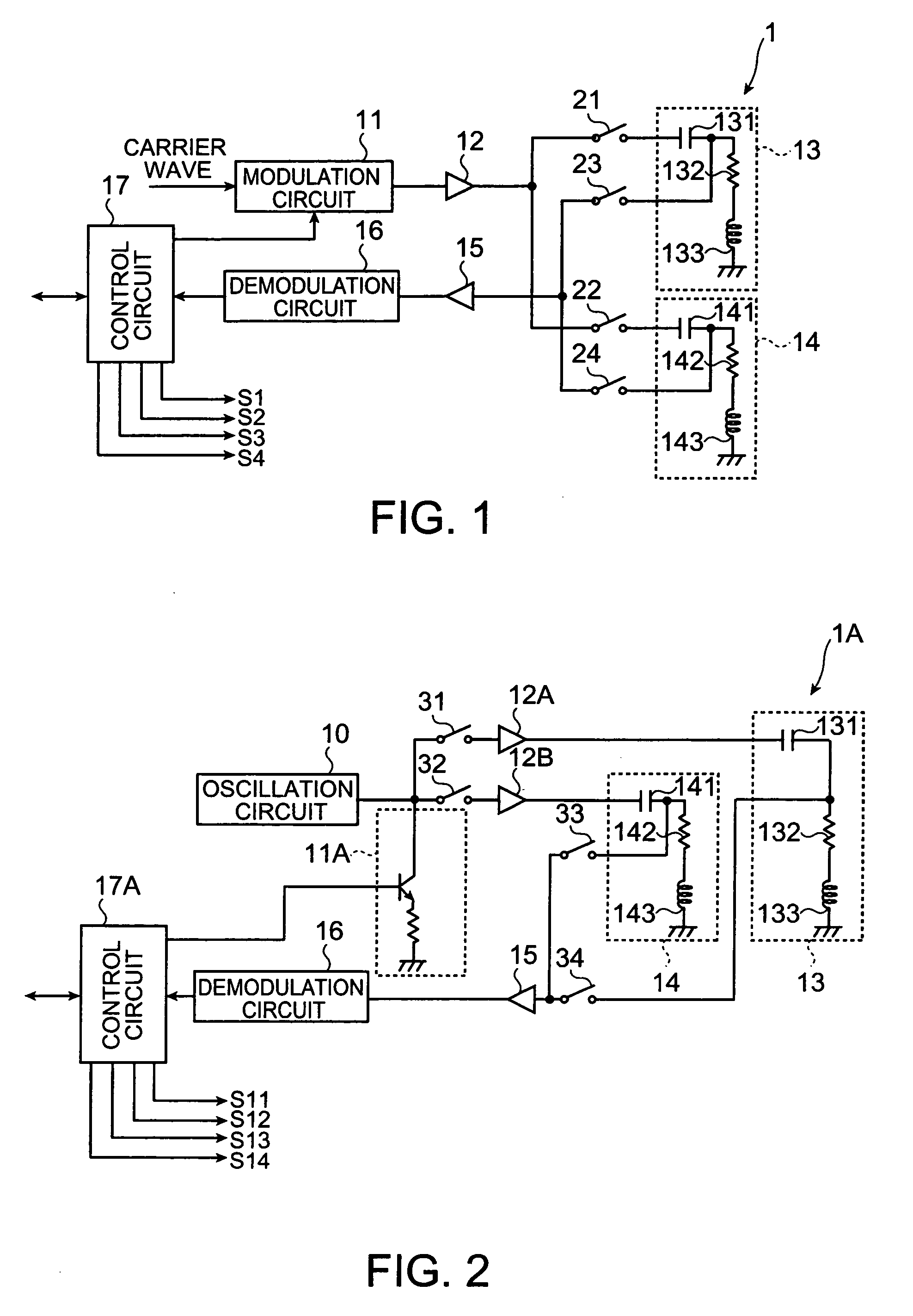
[0031]FIG. 1 is a circuit diagram showing a configuration of a reader / writer according to a first embodiment of the invention. A reader / writer 1 according to the first embodiment can perform a two-way communication with an unshown contactless tag through electromagnetic induction and can supply electric power to the contactless tag.
[0032] Accordingly, the reader / writer 1 has a modulation circuit 11, a power amplifier circuit 12, antenna circuits 13 and 14, an amplifier circuit 15, a demodulation circuit 16 and a control circuit 17 as shown in FIG. 1.
[0033] The reader / writer 1 further has switches 21, 22 between the power amplifier circuit 12 and the antenna circuits 13, 14, and switches 23, 24 between the amplifier circuit 15 and the antenna circuits 13, 14.
[0034] The modulation circuit 11 modulates a carrier wave from an oscillation circuit (not shown in the figure) according to a send data outputted from the control circuit 17. The power amplifier circuit 12 amplifies the power...
second embodiment
[0056]FIG. 2 is a circuit diagram showing a configuration of the reader / writer according to a second embodiment of the invention.
[0057] A reader / writer 1A according to the second embodiment can perform the two-way communication with an unshown contactless tag through the electromagnetic induction and can supply the electric power to the contactless tag.
[0058] Accordingly, the reader / writer 1A has an oscillation circuit 10, a modulation circuit 11A, power amplifier circuits 12A and 12B, the antenna circuits 13 and 14, the amplifier circuit 15, the demodulation circuit 16 and the control circuit 17 as shown in FIG. 2.
[0059] The reader / writer 1A further has switches 31, 32 correspondingly in the inputs side of the power amplifier circuit 12A and 12B, and switches 33, 34 between the amplifier circuit 15 and the antenna circuits 13, 14.
[0060] The oscillation circuit 10 generates a carrier wave with a predetermined frequency. The modulation circuit 11A modulates the carrier wave from ...
third embodiment
[0076]FIG. 5 is a circuit diagram showing a configuration of a reader / writer according to a third embodiment of the invention.
[0077] A reader / writer 1B according to the third embodiment can perform the two-way communication with an unshown contactless tag through the electromagnetic induction and can supply the electric power to the contactless tag.
[0078] Accordingly, the reader / writer 1B has the modulation circuit 11, the power amplifier circuit 12, matching circuits 51 and 52, antenna coils 53,54, the amplifier circuit 15, the demodulation circuit 16 and the control circuit 17B as shown in FIG. 5.
[0079] The reader / writer 1B further has switches 61, 62 between the matching circuits 51 and 52 and the corresponding antenna coils 53, 54, and switches 63, 64 between the amplifier circuit 15 and the antenna coils 53, 54.
[0080] The modulation circuit 11 modulates the carrier wave from the oscillation circuit (not shown in the figure) according to a send data outputted from the contro...
PUM
 Abstract
Description
Claims
Application Information
 - R&D
- Intellectual Property
- Life Sciences
- Materials
- Tech Scout
- Unparalleled Data Quality
- Higher Quality Content
- 60% Fewer Hallucinations
Browse by: Latest US Patents, China's latest patents, Technical Efficacy Thesaurus, Application Domain, Technology Topic, Popular Technical Reports.
© 2025 PatSnap. All rights reserved.Legal|Privacy policy|Modern Slavery Act Transparency Statement|Sitemap|About US| Contact US: help@patsnap.com


