Method for reducing auto-fluorescence signals in confocal Raman microscopy

a raman microscopy and autofluorescence technology, applied in the field of reducing autofluorescence signals in confocal raman microscopy, can solve the problems of excessive tissue biopsy, difficult early detection, and dramatic increase in the incidence of skin cancer, and achieve the effect of strong potential for non-invasive diagnosis of skin cancer and strong potential for us

Inactive Publication Date: 2006-04-20
HANBAT NAT UNIV IND ACADEMIC COOPERATION FOUND
View PDF1 Cites 11 Cited by
  • Summary
  • Abstract
  • Description
  • Claims
  • Application Information

AI Technical Summary

Benefits of technology

[0010] Raman spectroscopy has strong potential for providing non-invasive diagnosis of skin cancer. In the present invention, confocal Raman microscopy was applied to the dermatological diagnosis for one of the most common skin cancer, basal cell carcinoma (BCC). Tissues were obtained from 10 BCC patients using a routine biopsy and used for confocal Raman measurements. Auto-fluorescence signals from tissues, which interfere with the Raman signals, were greatly reduced using a confocal slit adjustment. Distinct Raman band differences between normal and BCC tissues for the amid

Problems solved by technology

Recently, the incidence of skin cancer has dramatically increased due to the excessive exposure of skin to UV radiation caused by ozone layer destruction, environmental contamination and so on.
Unfortunately, early detection is difficult because diagnosis is still based on morphological inspection by a pat

Method used


Image

  • Method for reducing auto-fluorescence signals in confocal Raman microscopy
  • Method for reducing auto-fluorescence signals in confocal Raman microscopy
  • Method for reducing auto-fluorescence signals in confocal Raman microscopy

Examples


example 1

Skin Tissue Preparations

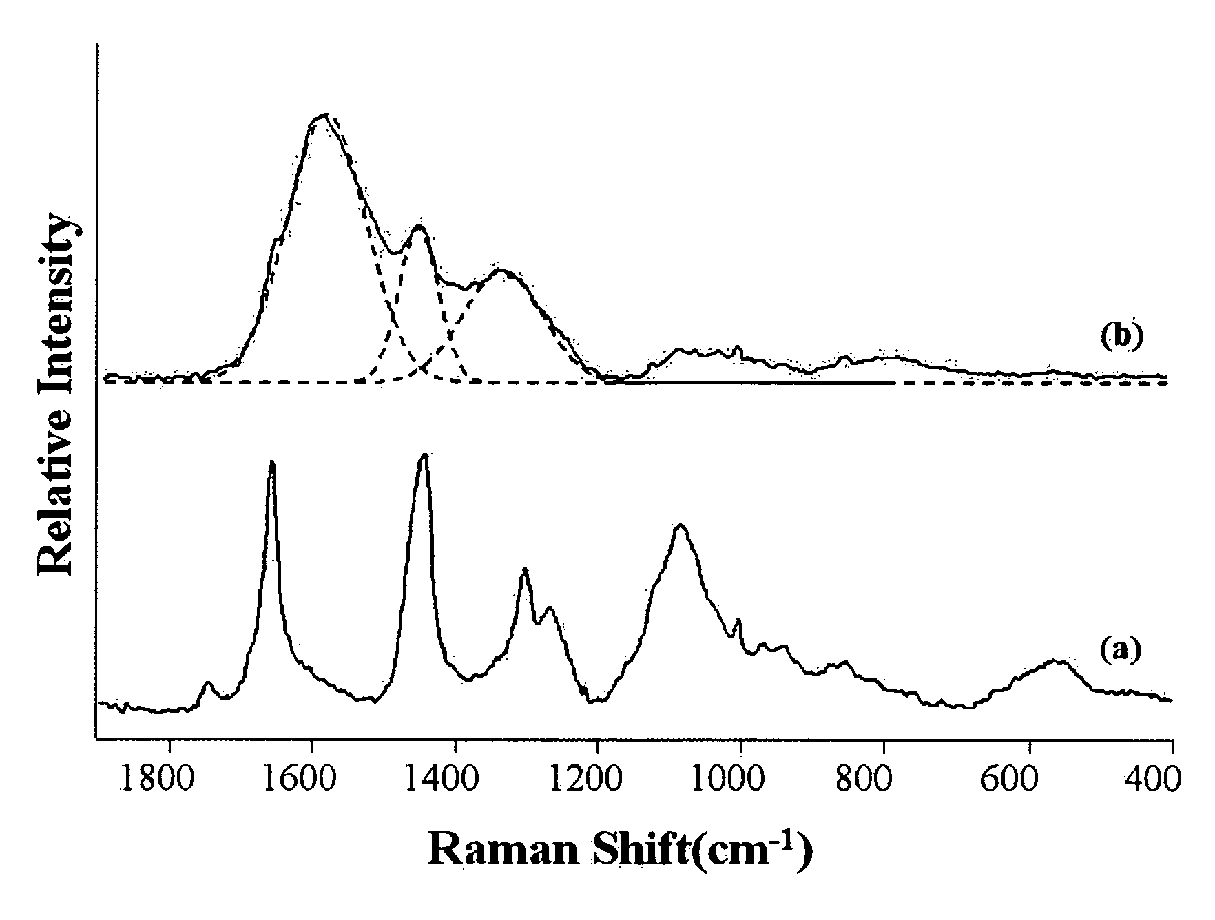
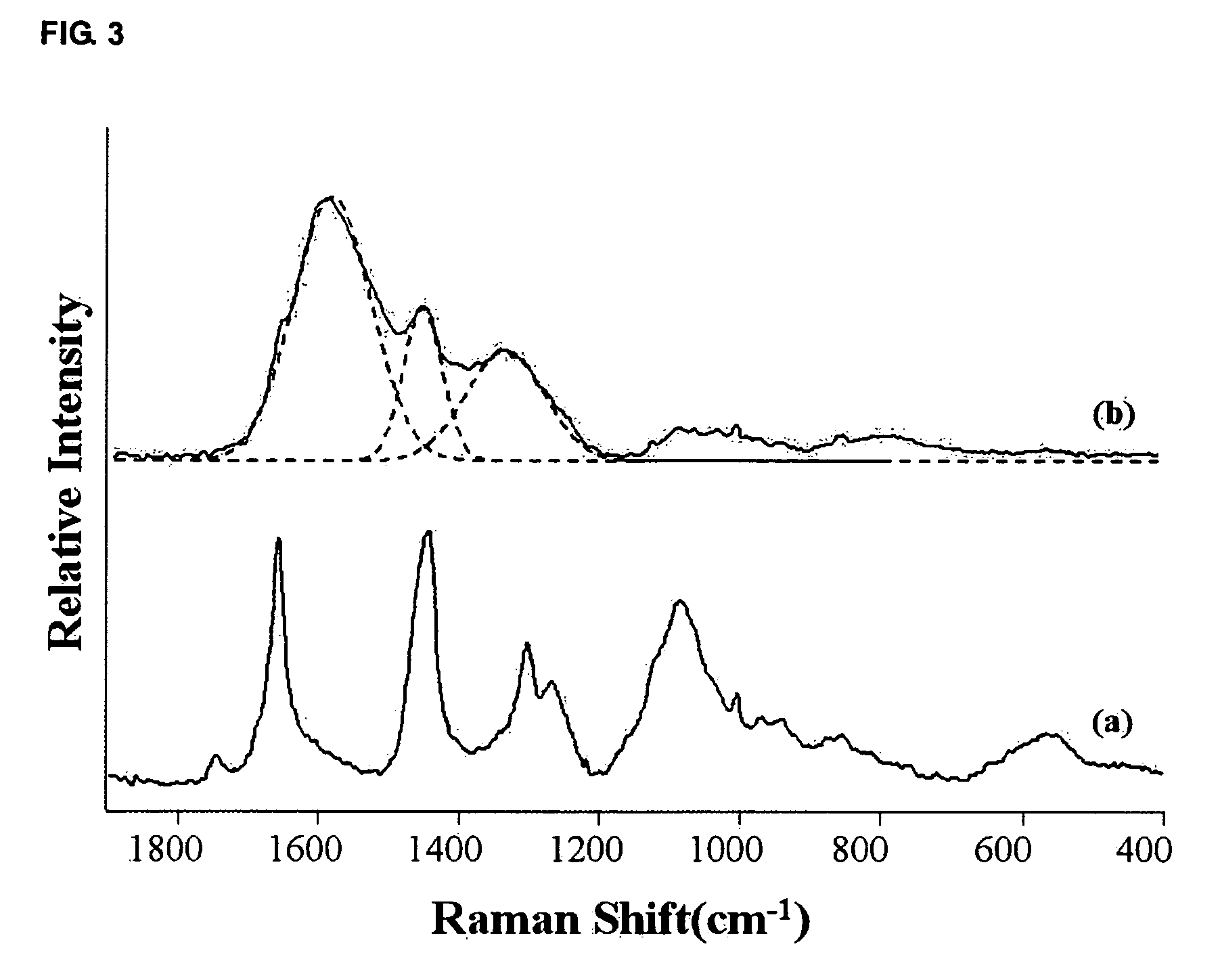
[0033] Skin tissue samples were obtained from the Dermatologic Department of Korea University Hospital in Korea. BCC tissues used for confocal Raman measurements were obtained from 10 patients using a routine biopsy. Cross-sections 20 μm thick were cut with a microtome at −20° C., and frozen sections were stored in liquid nitrogen before use. Two thin sections were cut for the experiments. One section was used for confocal Raman profiling experiments and the other section was stained with H&E and sent to an expert pathologist for a routine cancer diagnosis. The H&E section was also used as a Raman reference to locate the boundaries between the different skin-layers in the unstained section. In the present paper, characteristic Raman spectra for three different area of BCC tissues will be introduced.

example 2

Confocal Raman Measurements

[0034] Confocal Raman measurements were performed using a Renishaw 2000 Raman microscope system. A Spectra Physics argon ion laser operating at λ=514.5 nm was used as the excitation source with a laser power of approximately 20 mW. The Rayleigh line was removed from the collected Raman scattering by a holographic notch filter located in the collection path. Raman scattering was detected using a charge-coupled device (CCD) camera at a spectral resolution of 4 cm−1. An additional CCD camera was fitted to an optical microscope to obtain optical images of skin tissue samples. A two-slit confocal arrangement was used to reduce background Raman scattering from the unfocused laser beams. All Raman spectra were measured in the confocal mode to remove out-of-focus signals (Lee et al., J Raman Spectrosc 2003, 34, 737-742). In the Raman system, the function of the pinhole was replaced by the cooperation of the entrance slit and the pixels in the CCD detector. The fi...


PUM


Abstract

The present invention relates to a method for reducing auto-fluorescence signals from a sample tissue in confocal Raman microscopy and to a method for diagnosing skin cancers using the same method. Raman spectroscopy has strong potential for providing non-invasive diagnosis of skin cancer. Auto-fluorescence signals from tissues, which interfere with the Raman signals, were greatly reduced using a confocal slit adjustment. Distinct Raman band differences between normal and BCC tissues for the amide I mode, the amide III mode and the PO2 symmetric stretching mode, showed that the present invention has strong potential for use as a dermatological diagnostic tool without the need for statistical treatment of spectral data. It was also possible to precisely differentiate BCC tissue from surrounding non-cancerous tissue using the confocal Raman depth profiling technique. According to the present invention, confocal Raman microscopy can provide a novel method for dermatological diagnosis since direct observations of spectral differences between normal and BCC tissues are possible.

Description

CROSS-REFERENCE TO RELATED PATENT APPLICATION [0001] This application claims the benefit of Korean Patent Application No. 10-2004-0083980, filed on Oct. 20, 2004, in the Korean Intellectual Property Office, the disclosure of which is incorporated herein in its entirety by reference BACKGROUND OF THE INVENTION [0002] 1. Field of the Invention [0003] The present invention relates to a method for reducing auto-fluorescence signals from a sample tissue in confocal Raman microscopy and to a method for diagnosing skin cancers using the same method. [0004] 2. Description of the Related Art [0005] Advances in spectroscopic technology over the past few decades have had a significant impact on the area of cancer research. Technologies such as FT-IR, Raman and confocal fluorescence microscopy have been used to elucidate the origin and progression of cancer (Jackson, M. Faraday Discuss 2004, 126, 1-18; Yano et al. Analyt Biochem 2000, 287, 218-225). These technologies have also been used for th...

Claims


Application Information

Patent Timeline
IPC IPC(8): A61B6/00
CPCG01N21/65A61B5/00
Inventor OH, CHIL HWANGWEON, DAE GABKIM, HYO JINPARK, JEUNG HEECHOO, JAE BUMCHUNG, HOI EILCHOI, JUNG HYUN
Owner HANBAT NAT UNIV IND ACADEMIC COOPERATION FOUND
Why Eureka
Try Eureka