
Optical disk and production method therefor

a production method and optical disk technology, applied in the field of optical disks, can solve the problems of inability to absorb pressure, inability to react with bisphenol a, and remained unreacted, and achieve the effects of easy and inexpensive production, low substrate warpage, and high-definition images

Inactive Publication Date: 2006-04-20
TOPPAN PRINTING CO LTD +1
View PDF7 Cites 13 Cited by
  • Summary
  • Abstract
  • Description
  • Claims
  • Application Information

AI Technical Summary

Benefits of technology

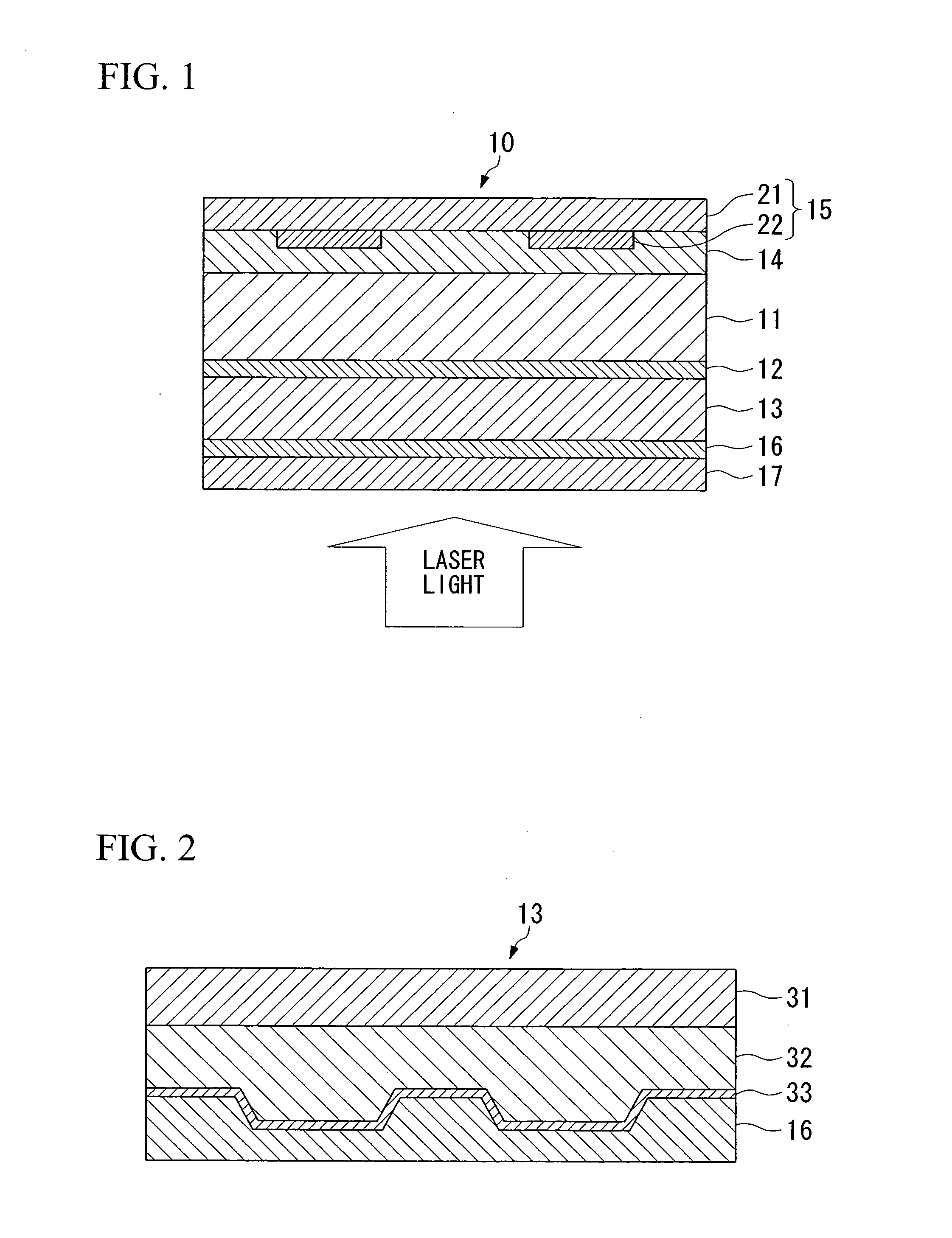
[0012] Since this type of optical disk uses a substrate included biodegradable resin or polyolefin resin for the substrate, it has a minimal effect on the environment during disposal while retaining performance that is equal to that of optical disks of the prior art. In addition, since a recording layer is provided on both sides of the substrate or a recording layer is provided on one side of the substrate while a printing layer is provided on the other side of the substrate, and the recording layer and printing layer have a base material layer included a non-hydrophilic film, water absorption and moisture absorption of the substrate can be suppressed, thereby making it possible to suppress warping and other deformation of the optical disk.
[0013] In addition, if the substrate additionally has a protective layer that protects the aforementioned recording layer, then together with preventing scratching of the recording layer, water absorption and moisture absorption of the substrate can be further suppressed, and warping and other deformation of the optical disk can be further suppressed.
[0014] In addition, if a release layer is provided between the substrate and the recording layer and / or printing layer, since the substrate and recording layer and / or printing layer can be separated and disposed of separately at the time of disposal, each layer can be disposed of in accordance with the material of which it is made, thereby making it possible to further reduce the effect on the environment.
[0020] In this type of the manufacturing method of an optical disk, since the substrate, recording layer and as necessary, printing layer and protective layer, are formed by prefabricating their corresponding sheets in advance followed by their lamination, an optical disk having little substrate warping can be produced easily and inexpensively.
[0021] In addition, since the manufacturing method has fabricating a printing sheet by carrying out printing on a printing base material in advance followed by laminating it to the substrate, highly detailed images can be obtained easily and inexpensively. In addition, variable information, such as sequentially changing serial numbers, that differs for each disk can be imparted by printing onto the optical disk.

Problems solved by technology

However, since bisphenol A is used as monomer for the aforementioned polycarbonate and epoxy resin substrate materials, unreacted bisphenol A remained even after polymerization.
The use of glass has been considered for use as a substrate material since it does not contain bisphenol A and satisfactory optical characteristics in the form of high transmittance.
However, glass substrates have problems in terms of strength in that they are unable to accommodate the pressure and stress during production and use due to limitations on disk thickness.
However, in the production of this optical disk since surface irregularities in the form of pits are stamped directly onto the surface of a disk-shaped substrate that has been punched out from an extruded sheet (refer to paragraphs 0018 through 0019), there is the problem of difficulty in stamping the pits.
In addition, there is also the problem of increased susceptibility to warping of the substrate due to moisture absorption resulting in impaired reading of information.
Another problem with conventional optical disks is that, although silk screen printing has mainly been used in the case of printing characters or images on the surface, there is the problem of the difficulty in obtaining highly detailed images with silk screen printing.
In addition, in the case of silk screen printing, in order to print serial numbers or other different characters and images for each disk, it is necessary to change the form plate each time, thereby resulting in the problem of being unable to in fact impart variable information by printing to conventional optical disks.

Method used


Image

  • Optical disk and production method therefor
  • Optical disk and production method therefor
  • Optical disk and production method therefor

Examples


example 1

[0135] (Fabrication of Printing Sheet)

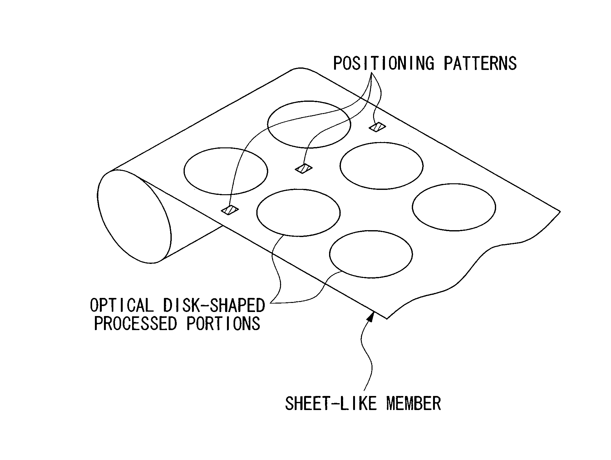
[0136] Gravure printing was carried out using biodegradable polyester printing ink (Dainichiseika Color and Chemicals, Biotech Color HGP) on a polylactic acid film drawn to a thickness of 0.04 mm (Mitsubishi Plastics, Ecoloju) to obtain a printing sheet on which was printed markings indicating the type of optical disk, additional information relating to the optical disk, decorative images and so forth.

[0137] (Fabrication of Substrate Sheet)

[0138] Polyethylene was molten extrusion coated onto both sides of a polylactic acid film drawn having a thickness of 1.0 mm (Mitsubishi Plastics, Ecoloju) after carrying out simple adhesive treatment such as corona treatment, followed by preliminarily forming a release layer having a thickness of 0.015 mm.

[0139] (Fabrication of Recording Layer Sheet)

[0140] Surface irregularities corresponding to tracks and information pits were transferred to a copper-plated roll after which the roll was chrome-plated fr...

example 2

[0153] With the exception of changing the fabrication of the recording layer sheet as described below, optical disks were obtained in the same manner as Example 1.

[0154] (Fabrication of Recording Layer Sheet)

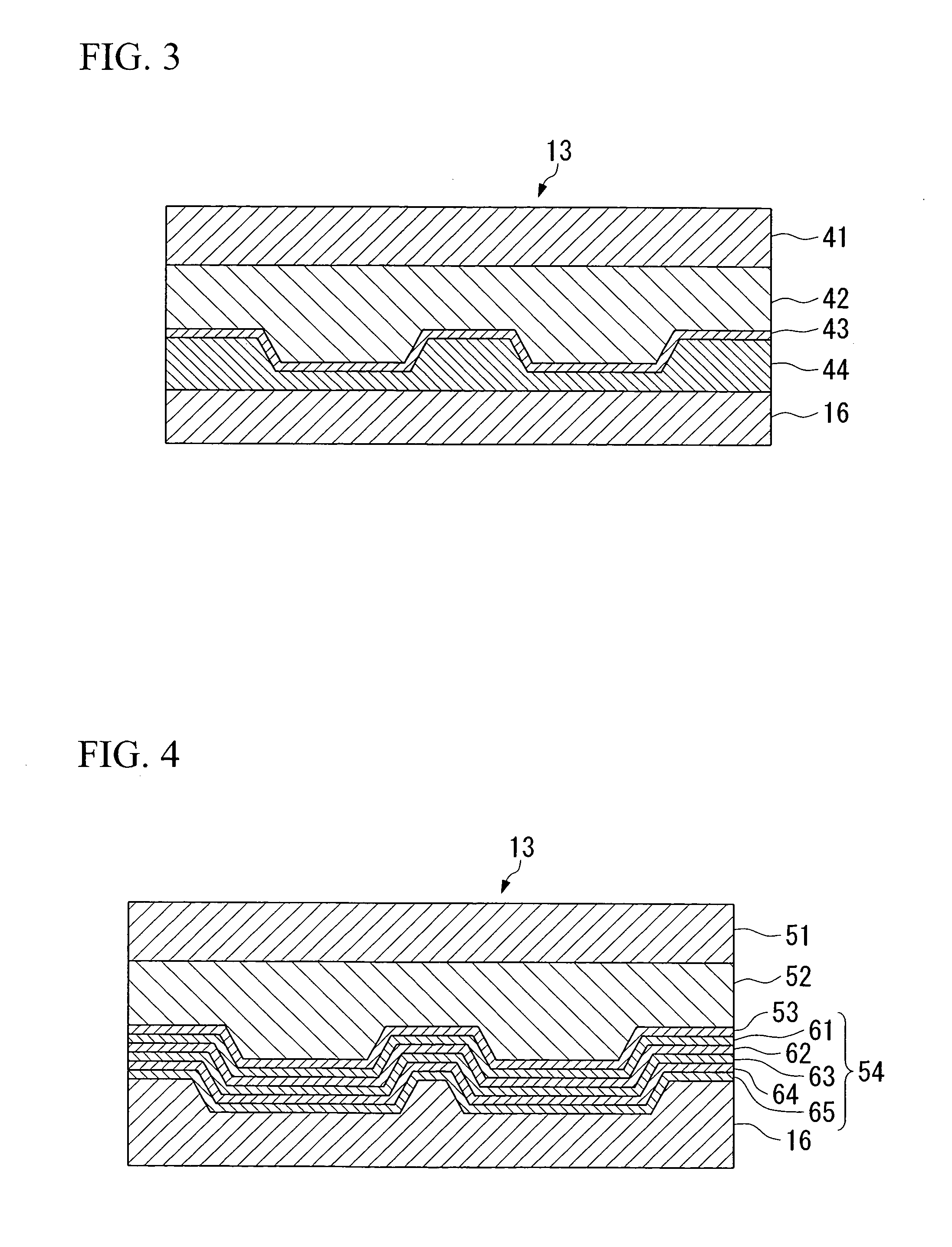
[0155] Surface irregularities corresponding to tracks and information pits were transferred to a copper-plated roll after which the roll was chrome-plated from above to obtain a transfer mold.

[0156] An ultraviolet-cured resin was coated onto a high-density polyethylene film drawn to a thickness of 0.05 mm with a die coater to a thickness of 0.1 mm, and the transfer mold was pressed against its surface to transfer the surface irregularities to the surface of the ultraviolet-cured resin.

[0157] Next, the ultraviolet-cured resin was irradiated with ultraviolet light to cure the ultraviolet-cured resin and form tracks.

[0158] Next, aluminum was vacuum deposited on the tracks and a light reflecting layer having a thickness of 60 nm was formed.

[0159] Next, a cyanine pigment was co...

example 3

[0163] With the exception of changing the fabrication of the recording layer sheet as described below, optical disks were obtained in the same manner as Example 1.

[0164] (Fabrication of Recording Layer Sheet)

[0165] Surface irregularities corresponding to tracks were transferred to a copper-plated roll after which the roll was chrome-plated from above to obtain a transfer mold.

[0166] An ultraviolet-cured resin was coated onto a high-density polyethylene film drawn to a thickness of 0.05 mm with a die coater to a thickness of 0.1 mm, and the transfer mold was pressed against its surface to transfer the surface irregularities to the surface of the ultraviolet-cured resin.

[0167] Next, the ultraviolet-cured resin was irradiated with ultraviolet light to cure the ultraviolet-cured resin and form tracks.

[0168] Next, aluminum was vacuum deposited on the tracks and a light reflecting layer having a thickness of 60 nm was formed.

[0169] Next, an SiO2 film having a thickness of 220 nm, a ...


PUM

PropertyMeasurementUnit
thicknessaaaaaaaaaa
thicknessaaaaaaaaaa
thicknessaaaaaaaaaa

Abstract

An optical disk (10) of the present invention comprises a substrate (11) included a biodegradable resin or polyolefin resin, a recording layer (13) provided on at least one side of the substrate (11), and a printing layer (15) provided on the other side of substrate (11), wherein recording layer (13) and printing layer (15) have a base material layer (recording layer base material, printing base material (21)) included a non-hydrophilic film. This type of optical disk (10) has performance equal to that of conventional optical disks, has a minimal effect on the environment during disposal and is able to suppress warping of the substrate. In addition, a manufacturing method of an optical disk of the present invention comprises a recording layer sheet fabrication step in which a recording layer sheet is fabricated by forming tracks on a recording layer base material, a printing sheet fabrication step in which a printing sheet is fabricated by carrying out printing on a printing base material, and respective lamination steps in which the substrate sheet, recording layer sheet and printing sheet are laminated.

Description

TECHNICAL FIELD [0001] The present invention relates to an optical disk such as a Blu-ray disk (BD) or digital versatile disk (DVD) and manufacturing method of the same. BACKGROUND ART [0002] Polycarbonate, epoxy resin and so forth have frequently been used as the substrate materials of conventional optical disks since these substrate materials are required to have low contents of extraneous materials and impurities, high permeability and low double refractive index to enable stable reading and writing, a low moisture absorption rate and superior heat resistance to prevent deformation of the optical disk, as well as high fluidity and superior mold release to facilitate molding processing (Japanese Unexamined Patent Application, First Publication No. 05-258349). [0003] However, since bisphenol A is used as monomer for the aforementioned polycarbonate and epoxy resin substrate materials, unreacted bisphenol A remained even after polymerization. Due to the growing interest in environme...

Claims


Application Information

Patent Timeline
Patent Type & Authority Applications(United States)
IPC IPC(8): G11B7/00G11B7/24024G11B7/24027G11B7/24035G11B7/24047G11B7/24094G11B7/24097G11B7/2533G11B7/2539G11B7/26
CPCB32B37/12B32B38/06G11B7/24094B32B2307/7163B32B2429/02B32B38/145G11B7/2539G11B7/26
Inventor KINOSHITA, TOSHIROKOBAYASHI, AKIHIKOSASAKI, NOBORUARISAWA, MAKOTOSEKIGUCHI, MAMORUHIROSHI, HIROSHIYAMASAKI, YOSHIMORIOSATO, KIYOSHIYAMAGAMI, TAMOTSUWATANABE, HIDETOSHI
Owner TOPPAN PRINTING CO LTD
Learn More