
Solid-state lighting apparatus for navigational aids

a solid-state lighting and navigational aid technology, applied in landing aids, lighting support devices, light source combinations, etc., can solve the problems of shortening the useful life of leds, difficult to achieve incandescent lamps, and luminous intensity does not meet the needs of runway edge lighting, etc., to achieve the effect of improving heat dissipation, increasing output power, and increasing curren

Inactive Publication Date: 2006-04-20
BWT PROPERTY
View PDF19 Cites 90 Cited by
  • Summary
  • Abstract
  • Description
  • Claims
  • Application Information

AI Technical Summary

Benefits of technology

[0009] It is therefore an objective of the present invention to provide an airport / navigational lighting apparatus which can solve all the above mentioned problems.
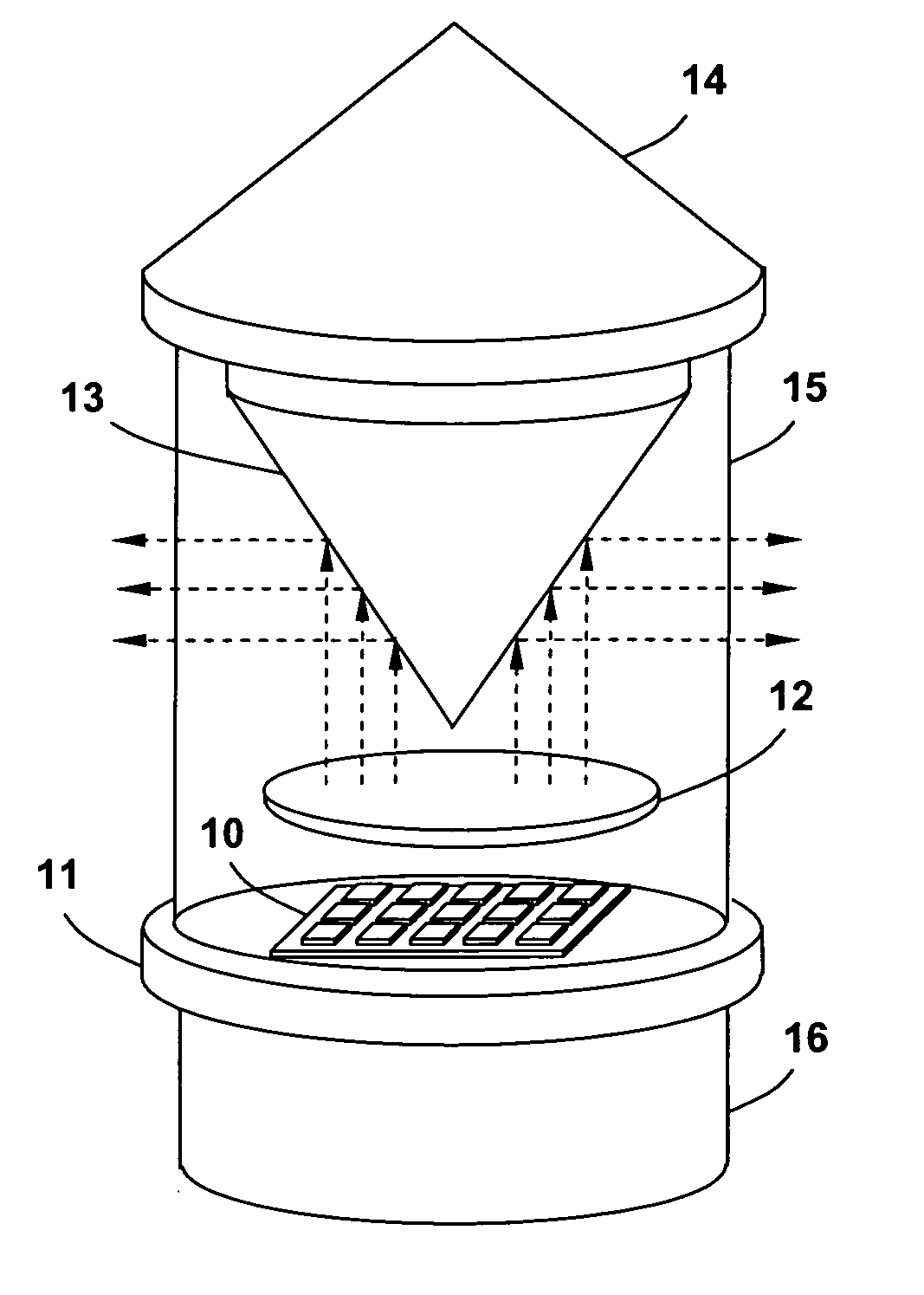
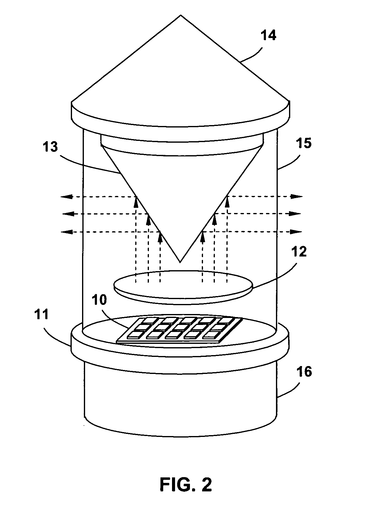
[0010] To achieve the above and other objectives, the current invention in at least some of its embodiments utilizes newly developed high intensity LEDs or LED arrays with a chip-on-board (COB) package, in which the LED chips are directly surface-mounted on a thermal conductive substrate for improved heat dissipation. In one aspect, the COB package allows much higher current to be applied on the LED chip to increase its output power. In another aspect, the packing density of the LED chips can be greatly increased by over one order of magnitude. As a result, the LED lighting apparatus disclosed in the current invention achieves a luminous intensity of several hundred or even several thousand candelas.
[0011] In various preferred embodiments, the following description will provide detailed optical and mechanical design for unidirectional, bidirectional as well as omni-directional navigational lights that are built on COB packaged LEDs or LED arrays to meet high luminous intensity requirements. Color control and chromatic management is realized by integrating multiple wavelength LED chips into one lighting apparatus and controlling the relative intensity of those LED chips. Due to its improved heat dissipation capability, the LED lighting apparatus disclosed in the current invention can work in continuous mode with no modulation, thus completely eliminating the risk of vertigo.

Problems solved by technology

That luminous intensity does not meet the needs for runway edge lighting, approach lighting, threshold / end lighting, and obstruction / beacon lighting.
That is difficult to achieve in a conventional incandescent lamp, where the color is usually defined by the color of the glass cover.
Unfortunately, during the lifetime of an LED, not only will the light intensity decay gradually, but also, its chromatic characteristics will change, which can further shorten the useful lifetime of the LED.
However, even though the naked human eyes can not sense the fast flickering (modulation), the modulation creates an artificial illusion to a pilot wearing night vision goggles and may cause dizziness and vertigo.

Method used


Image

  • Solid-state lighting apparatus for navigational aids
  • Solid-state lighting apparatus for navigational aids
  • Solid-state lighting apparatus for navigational aids

Examples


Embodiment Construction

[0020] Preferred embodiments of the present invention will now be set forth in detail with reference to the drawings, in which like reference numerals refer to like elements throughout.

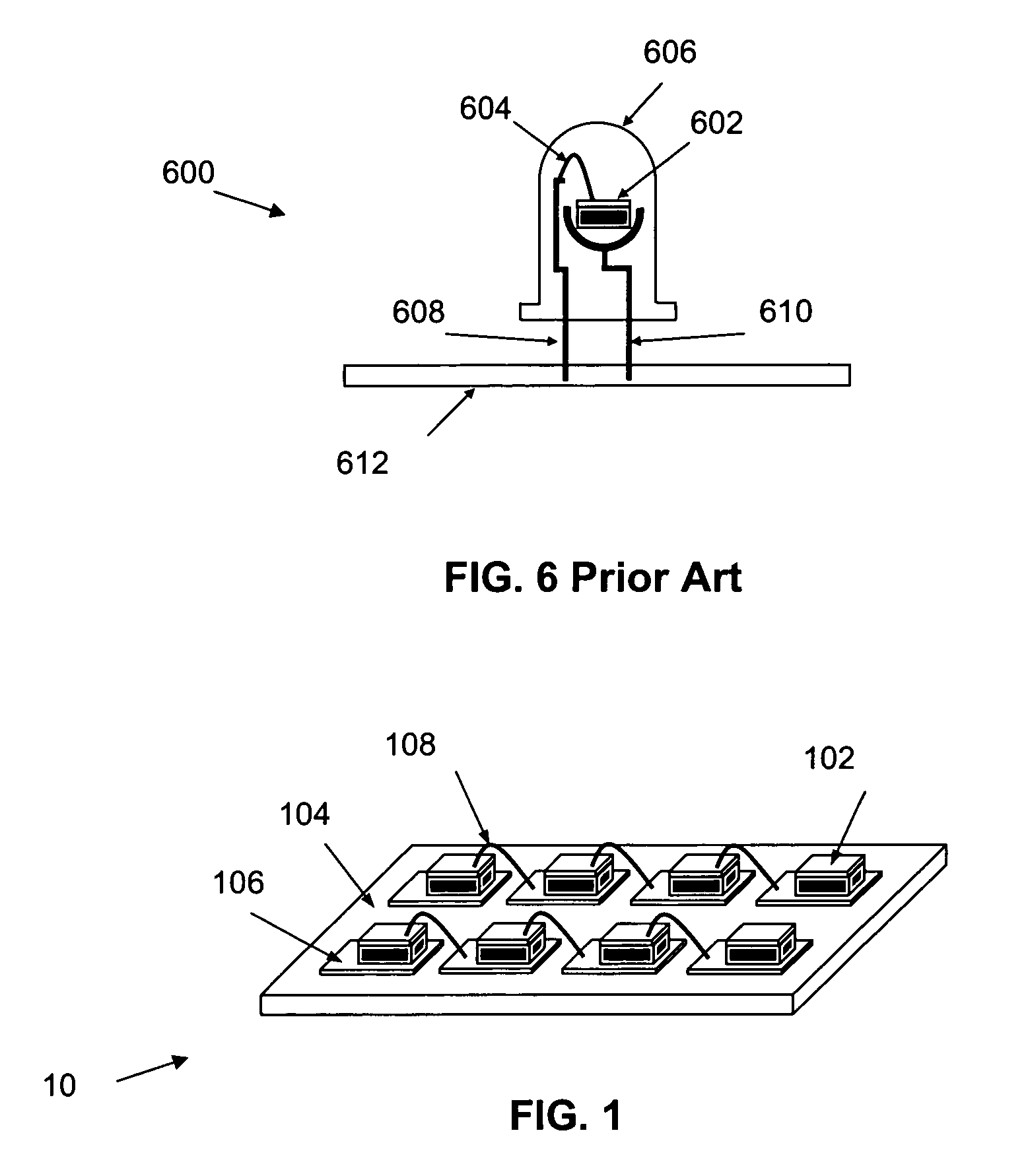
[0021] A traditional LED light utilizes a small LED chip mounted on a reflector cup as shown in FIG. 6. That kind of package is generally referred to as T-pack. In the traditional LED light 600, an LED chip 602 and a gold wire 604 are enclosed in an epoxy lens 606. The LED is attached by a cathode 608 and an anode 610 to a printed circuit board (substrate) 612.

[0022] The traditional LED light 600 has very high thermal resistance (>200K / W) due to a poor heat sink. Thus, its input power is limited to <0.1-Watt to keep the operating temperature of the PN junction at <120° C. safety level. Due to the limitation of achievable individual LED brightness, a large number of LED lights are required to meet the luminous intensity requirements, which results in a large footprint due to the size of each T-pack d...


PUM


Abstract

A high intensity solid-state lighting apparatus is disclosed for the application of navigational aids. In various embodiments based on the approach of chip-on-board packaged semiconductor light emitting elements, unidirectional, bidirectional as well as omni-directional navigational lights are configured to meet high luminous intensity requirements. They also provide additional utilities for generating multiple colors and flash patterns with the same light unit for lighting reconfiguration as well as creating new means of signaling. Another purpose of the current invention is to provide a light source which will not cause vertigo effects.

Description

REFERENCE TO RELATED APPLICATION [0001] The present application claims the benefit of U.S. Provisional Patent Application No. 60 / 619,012, filed Oct. 18, 2004, whose disclosure is hereby incorporated by reference in its entirety into the present disclosure.FIELD OF INVENTION [0002] The present invention generally relates to a lighting apparatus and more specifically to a high brightness solid-state lighting apparatus for navigational aids. BACKGROUND OF THE INVENTION [0003] Lighting is an integral part of the safety system for airports as well as helipads and waterways, providing guidance, signaling, and demarcation of aircraft runways and taxiways. The lighting system includes those elevated / in-pavement taxiway and runway lights, medium and high intensity approach lights, which can be further configured as edge, centerline, threshold / end, hold-line, stop bar, and runway guard lights. Light emitting diode (LED) sources have been identified to be the replacement for the conventional i...

Claims


Application Information

Patent Timeline
Patent Type & Authority Applications(United States)
IPC IPC(8): F21V21/00
CPCB64C2027/8236B64F1/20F21S10/06F21V9/10F21V23/04F21V23/0407F21W2111/06F21Y2101/02F21V7/041F21V5/007F21V13/12F21Y2115/10F21Y2113/13F21Y2107/90F21V9/40F21Y2105/16F21Y2105/10
Inventor WANG, SEAN XIAOLUTIAN, RONGSHENGLI, QINGXIONGLI, QUN
Owner BWT PROPERTY
Learn More