
Remote centre of motion positioner

a positioner and remote technology, applied in the field of robotics, can solve the problems of reducing vision perception from 3 dimensions to 2 dimensions, different and more difficult comparison of mis techniques, and reducing the effect of rigidity

Inactive Publication Date: 2015-05-12
KATHOLIEKE UNIV LEUVEN
View PDF12 Cites 178 Cited by
  • Summary
  • Abstract
  • Description
  • Claims
  • Application Information

AI Technical Summary

Benefits of technology

This solution results in a more compact, cost-effective, and stiffer RCM mechanism that reduces the risk of collisions and minimizes workspace above the patient, allowing for easier adjustment and improved dexterity during MIS procedures.

Problems solved by technology

The MIS techniques are different and more difficult compared with traditional open surgery.
The scaling of the motion is not easy to be predicted by a novice surgeon.
Secondly, the vision perception is degraded from 3 dimensions to 2 dimensions due to the imaging system.
However, in order to obtain sufficient range of motion and stiffness, the resulting RCM arm employs a huge amount of working space above the patient.
When two or more RCM arms cooperate to perform robotic MIS procedure, there is a great chance to hit the surgeon next to it or two arms will collide with each other during the manipulation.
It increases the cost and occupies significant space along the bedside.
This method will significantly reduce the stiffness and accuracy on the instrument holder and increases the size and weight of the whole arm.
The principal difficulty lies in the optimal choices between its size, payload, accuracy, and working radius.
However, due to the mounting of the actuators and its mechanisms in the small area, their payload and range of motion are relatively small.
On both big and small manipulators, due to their fixed remote centre of rotation, the adjustment of the remote centre point is obtained either by a mobile platform on the floor or a flexible arm (e.g. Fisso articulated arm, Baitella AG, Switzerland) coupled to the bed frame, which further increases the cost or decreases the stiffness.
In the latter RCM manipulator, the driving mechanism has a length equal to the total displacement of the linkages, which leads to a bulky arrangement and can lead to a lowered stiffness.
Furthermore, the location of the remote centre of motion is only adjustable by using an adjustable mounting fixture which further affects the stiffness of the manipulator.

Method used


Image

  • Remote centre of motion positioner
  • Remote centre of motion positioner
  • Remote centre of motion positioner

Examples


Embodiment Construction

Definitions

A “revolute joint” is a one degree of freedom kinematic pair which provides single axis rotation function.

A “prismatic joint” is a one degree of freedom kinematic pair which provides single axis linear motion capability.

“Movement axis of prismatic joint” is the line which coincides with the occurred motion of the kinematic pair of the prismatic joint

A “slide-revolute joint” is a two degrees of freedom joint which provides one degree of freedom rotation function along an axis of linear motion (one degree of freedom translation).

A “rigid link or link” is a solid object which connects with another rigid link via related joints to obtain relative motion.

A “belt clamp” is a physical fixation between the related link to the belt.

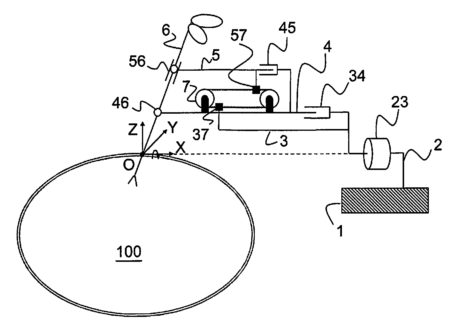
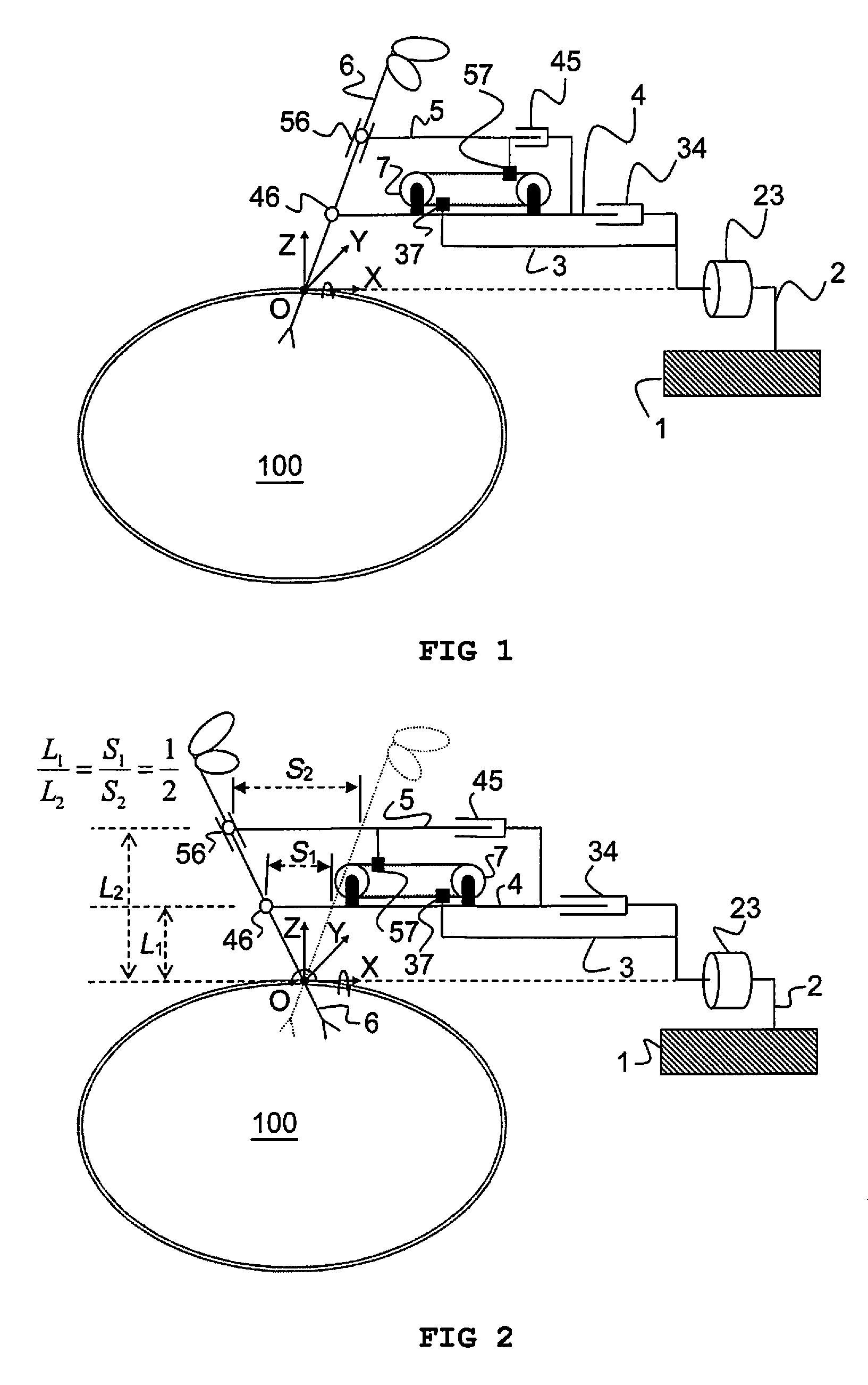
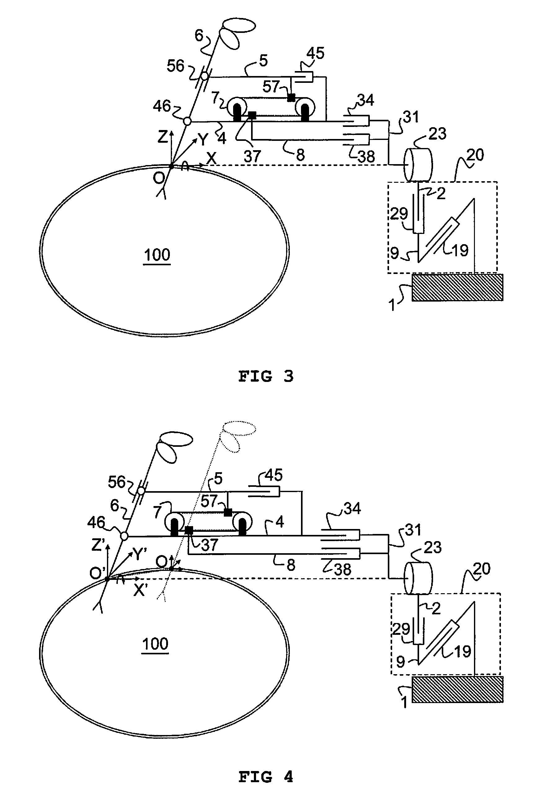
[0051]In a broad aspect an apparatus is provided for holding and manipulating an instrument about a predetermined remote centre of motion (rotation), which remains fixed during a given time period.

[0052]An exemplifying embodiment of an apparatus accordi...


PUM


Abstract

An apparatus having a member that revolves about a remote center of motion (RCM) and a base link coupled to a mounting fixture. A first and second link are pivotably coupled to the member at respective distances from the RCM and are translatable relative to the base link along a first direction, at a fixed ratio of displacement. The ratio of respective distances equals a fixed ratio of displacement. The apparatus has a translational motion generator for a first and second element along parallel opposing directions. The translational motion generator is disposed on the first link and enables motion parallel to the first direction. The base link is fixed in position, the first element is fixed to the base link and the second element is fixed to the second link, such that the first and second link may translate relative to the base link with fixed ratio of displacement.

Description

RELATED APPLICATIONS[0001]This application is a U.S. national phase entry under 35 U.S.C. §371 of PCT Application PCT / EP2010 / 056611, which claims priority to United Kingdom Application 0908368.4, filed May 15, 2009, and U.S. Provisional Application 61 / 216,276, filed May 15, 2009.FIELD OF THE INVENTION[0002]This invention is related to the field of robotics, in particular to robot assisted surgery.[0003]The present invention is directed to a remote centre of motion positioner used to support an instrument and provide a motion with fixed centre of rotation in a designated position where no physical object is present. It is very useful in performing robot assisted Minimally Invasive Surgery (MIS) to allow steering the surgical instrument inside a patient's body through a small incision on the patient's body.STATE OF THE ART[0004]In MIS procedure, a few small incisions (dia. 10 mm) are opened on a patient to allow instruments to be inserted therein. In one of the incisions, a laparoscop...

Claims


Application Information

Patent Timeline
Patent Type & Authority Patents(United States)
IPC IPC(8): B25J17/00A61B19/00
CPCA61B19/22A61B19/2203A61B2019/2242A61B2019/265Y10S901/16Y10S901/15Y10S901/21Y10T74/18088Y10T74/18056A61B34/30A61B34/70A61B34/71A61B2090/506Y10T74/18848Y10T74/20323
Inventor TANG, HSIAO-WEIVAN BRUSSEL, HENDRIKPEIRS, JANJANSSENS, THIERRY
Owner KATHOLIEKE UNIV LEUVEN
Learn More