
Toner, image forming apparatus using the same, and image forming method

a technology applied in the field of toner and image forming apparatus, can solve the problems of high cost, abnormal images brought about by such a toner-fixed aggregate, and loss of image color at that portion into white color

Inactive Publication Date: 2006-03-30
RICOH KK
View PDF21 Cites 35 Cited by
  • Summary
  • Abstract
  • Description
  • Claims
  • Application Information

AI Technical Summary

Benefits of technology

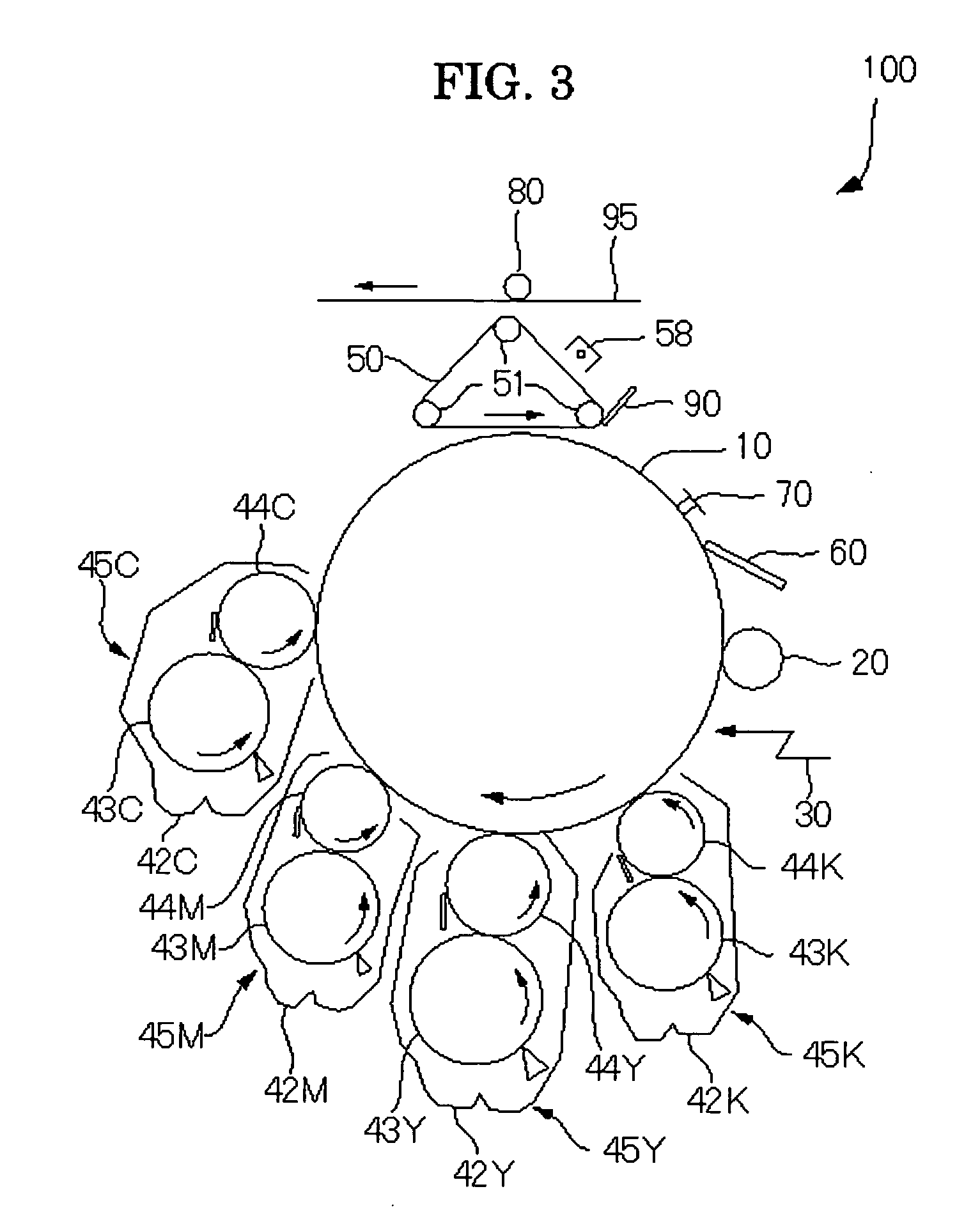
The present invention provides a toner that minimizes toner scattering in image forming apparatuses while still achieving good color reproduction for red colors. The toner also allows for a color image to be formed using multiple color toners, including yellow, magenta, cyan, and black. The image forming apparatus includes a latent electrostatic image bearing member, a latent electrostatic image forming unit, at least three developing units, and a fixing unit. The developing units include yellow, magenta, and cyan toners, which use specific pigments to achieve the desired colors. The toner is used in an image forming apparatus that forms a visible image by sequentially superimposing yellow, magenta, and cyan toners, or by using a mixed color of magenta and yellow toners. The toner is also used in a detachable process cartridge that integrates the latent electrostatic image bearing member, charging unit, developing unit, and cleaning unit. The technical effects of the invention include improved color reproduction, reduced toner scattering, and improved image quality.

Problems solved by technology

When the image is transferred onto a paper sheet, the toner-fixed aggregate serves as a spacer between the paper sheet and a photoconductor, resulting in a loss of color of the image at that portion into white color.
Particularly in color images, abnormal images easily stand out when comparing with monochrome images, and high resolution images having fine-textured tones and fine color reproductivity are required, and therefore abnormal images brought about by such a toner-fixed aggregate has become an issue.
This method is fairly effective in terms of preventing offset phenomenon of toners, however, it requires a device for supplying a releasing oil, and a large-sized image fixing unit must be prepared, resulting in high cost.
Color toners are more likely to cause offset phenomena than in monochrome toners which have no glossiness, and it is much more difficult to use an oilless toner in an image fixing unit and to use a minute amount of a releasing oil to coat a surface of a fixing roller.
In addition, when a releasing agent is included in a toner, adhesive strength of toner increases and transferring properties of toner against a transferring sheet degrades, causing a problem that interior part of an image forming apparatus is smeared because the releasing agent in the toner contaminates frictional electrification members such as carriers, and charge properties of the toner degrades.

Method used


Image

  • Toner, image forming apparatus using the same, and image forming method
  • Toner, image forming apparatus using the same, and image forming method
  • Toner, image forming apparatus using the same, and image forming method

Examples


example 1

[0191] An example of a toner produced by polymerization will be described.

[0192] To a reaction vessel provided with a stirrer and a thermometer, 683 parts of water, 11 parts of sodium salt of the sulfuric acid ester of methacrylic acid ethylene oxide adduct (ELEMINOL RS-30, manufactured by Sanyo Chemical Industries, Ltd.), 80 parts of styrene, 83 parts of methacrylic acid, 110 parts of butyl acrylate, 12 parts of butyl thioglycollate, and 1 part of ammonium persulphate were poured, and stirred at 400 rpm for 15 minutes to obtain a white emulsion. The white emulsion was heated, the temperature in the system was raised to 75° C. and the reaction was performed for 5 hours. Next, 30 parts of an aqueous solution of 1% ammonium persulphate was added, and the reaction mixture was matured at 75° C. for 5 hours to obtain an aqueous dispersion liquid of a vinyl resin or copolymer of styrene-methacrylic acid-butyl acrylate-sodium salt of the sulfuric acid ester of methacrylic acid ethylene ox...

example 2

[0220] Next, an example of a toner produced by kneading and pulverizing will be described.

[0221] In a dropping funnel, 15 mol of styrene as an addition polymerization reactive monomer, 5 mol of butyl methacrylate, and 0.2 mol of t-butylhydro-peroxide as a polymerization initiator were placed. To a flask equipped with a stainless stirrer, a flow-down condenser, a nitrogen inlet tube, and a thermometer, 15 mol of fumaric acid as a monomer reactive to both addition polymerization and polycondensation, 5 mol of anhydrous anhydrous trimellitic acid as a polycondensation reactive monomer, 5 mol of bisphenol A (2, 2) propylene oxide, 4 mol of bisphenol A (2, 2) ethylene oxide, and 6 mol of dibutyl tin oxide as an esterified catalyst were poured and stirred in an atmosphere of nitrogen at 135° C. while fall in drops of the preliminarily prepared mixture of the raw materials for addition polymerization reaction from the dropping funnel in 5 hours. After the dropping, the droplet was matured...

example 3

[0251] A toner and a developer were produced in the same manner as Example 2 except that the yellow toner pigment was changed to C.I. pigment yellow 155.


PUM


Abstract

An image forming apparatus of the present invention includes a latent electrostatic image bearing member, a latent electrostatic image forming unit configured to form a latent electrostatic image on the latent electrostatic image bearing member, at least three developing units each configured to develop the latent electrostatic image using a toner to form a visible image, a transferring unit configured to transfer the visible image on a recording medium, and an image fixing unit configured to the transferred image on the recording medium, in which the developing units respectively include any one of a yellow toner, a magenta toner, and a cyan toner, the magenta toner includes C.I. pigment red 269, and the yellow toner includes C.I pigment yellow 180 or C.I pigment yellow 155.

Description

BACKGROUND OF THE INVENTION [0001] 1. Field of the Invention [0002] The present invention relates to an image forming apparatus for forming color images based on electrostatic copying processes such as copiers, facsimiles, and printers. The present invention further relates to a toner used for the color image forming, an image forming apparatus using the toner, and an image forming method thereof. [0003] 2. Description of the Related Art [0004] In image forming based on an electrophotographic process, a latent image is formed by means of electrostatic charge on an image bearing member having a photosensitive layer which comprises photoconductive substances and the like, charged toner particles are adhered on the latent electrostatic image to form a visible image, and then the visible image is transferred onto a recording medium such as paper and fixed on the recording medium to be an output image. In recent years, there have been rapid developments from monochrome image technologies...

Claims


Application Information

Patent Timeline
Patent Type & Authority Applications(United States)
IPC IPC(8): G03G15/01
CPCG03G2215/0129G03G9/091
Inventor SHU, HYOAOKI, MITSUOMASUDA, MINORUHASEGAWA, KUMI
Owner RICOH KK
Learn More