
Membrane-electrode assembly for polymer electrolyte fuel cells, and polymer electrolyte fuel cell

a technology of electrolyte fuel cells and membrane electrodes, which is applied in the direction of cell components, cell component details, electrochemical generators, etc., can solve the problems of insufficient proton conductivity in the vicinity of its center, deterioration of the polymer electrolyte membrane or short circuiting of the electrodes, and damage to the membrane in the vicinity of the end portions of the electrode catalyst layer, etc., to prevent the deterioration of the polymer electrolyte membran

Inactive Publication Date: 2006-03-02
PANASONIC CORP
View PDF5 Cites 41 Cited by
  • Summary
  • Abstract
  • Description
  • Claims
  • Application Information

AI Technical Summary

Benefits of technology

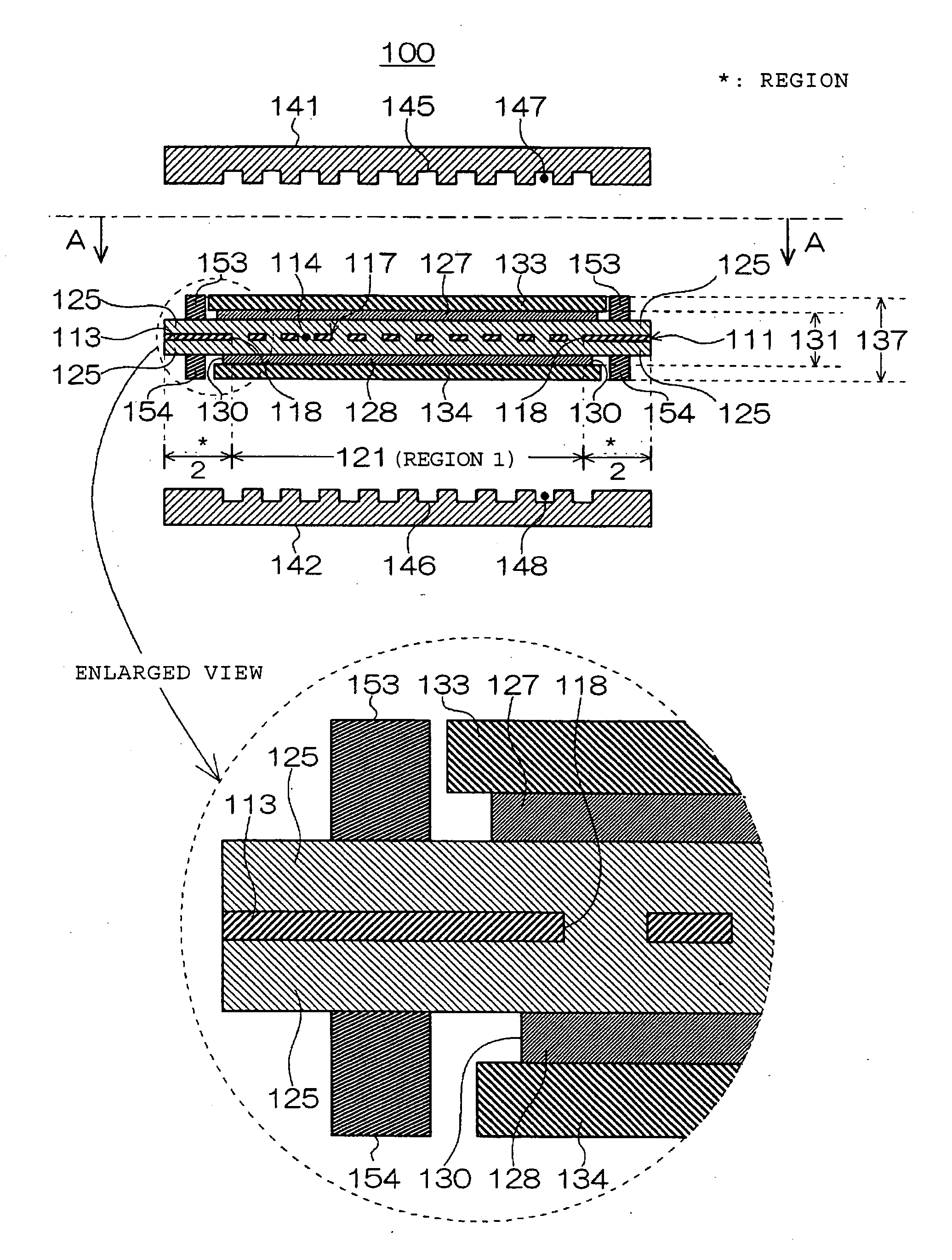
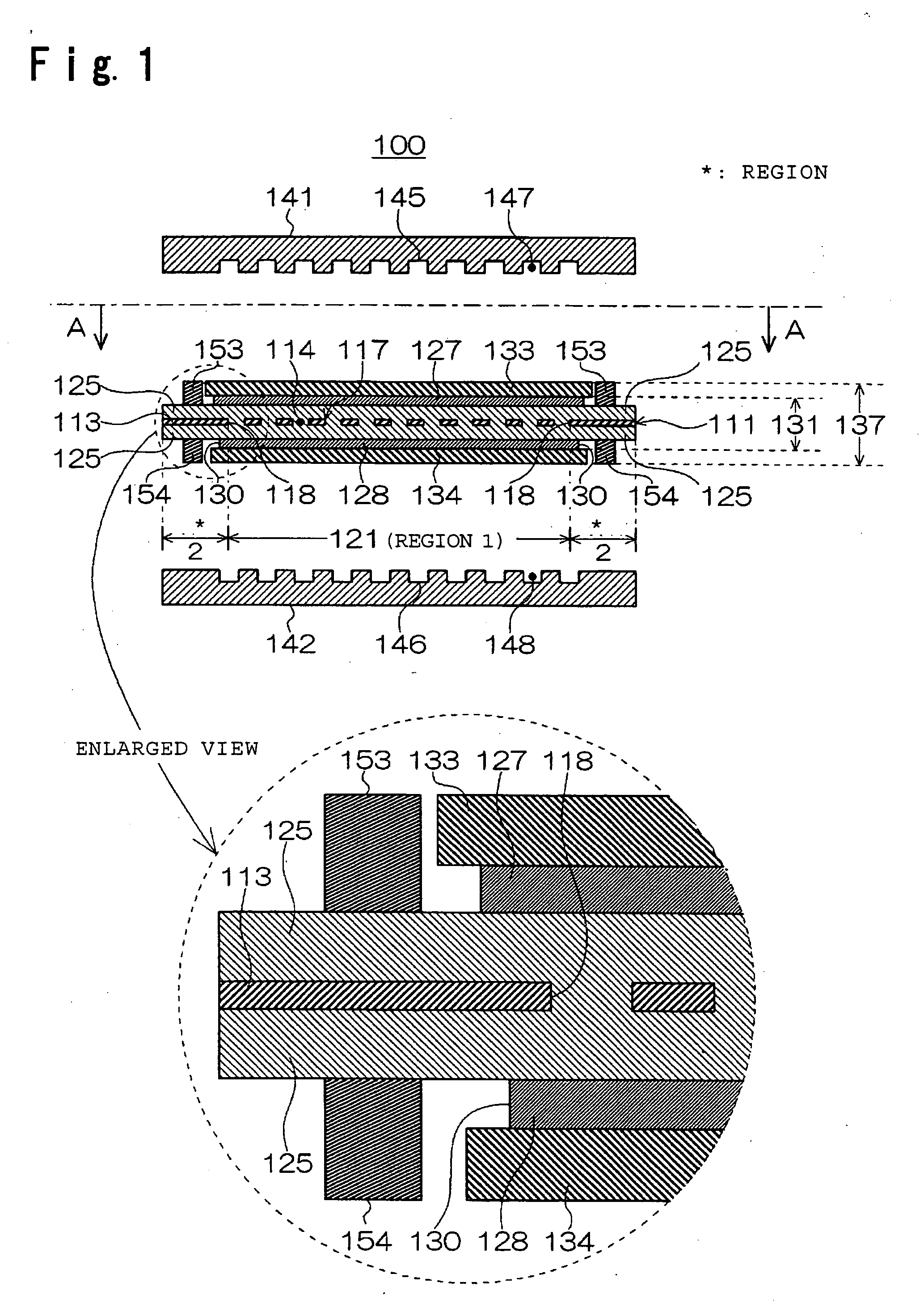
[0072] According to the present invention, the outer edges of the catalyst layers are disposed so as to be located in the second region so that the increase of gas leakage is suppressed even when the pressure is strongly exerted on the ends of electrode catalyst layers during bonding of the electrodes or even when the polymer electrolyte membrane is partly damaged by creep during the operation, whereby it is possible to prevent deterioration of the polymer electrolyte membrane or short circuiting of the electrodes caused by e.g. a local burning reaction. Thus, it is possible to provide a membrane-electrode assembly for fuel cells having a long life.

Problems solved by technology

However, in the case of this membrane-electrode assembly, there is a problem that membrane damage occurs in the vicinity of end portions inside of the reinforcing frames, though membrane damage at the end portions of the electrode catalyst layers can be suppressed.
However, in the case of this membrane, in the vicinity of the center, its strength is insufficient though resistance is low, and the gas permeability of the reinforced portions is suppressed but the suppression is still insufficient, and during a long-term operation, a defect of the membrane or short circuiting was likely to occur in the vicinity of the end portions of the electrode catalyst layers.
However, in such a case, there was such a problem that the proton conductivity in the vicinity of its center is insufficient though proton conductivity at the peripheral portions is low, whereby the power generation property is low.
However, in the case of this membrane-electrode assembly, it is difficult to prepare the assistant gaskets and to form catalyst layers precisely in it.
Therefore, there is such a problem that the catalyst layers are likely to overlap on the assistant gaskets to form defects.
However, misalignment may occur at the time of bonding the above gas diffusion layers with the ion exchange membrane, and the catalyst layers and the fluororesin sheets may overlap to form defects.
However, it is difficult to apply the catalyst layer with the same size as the opening, and the catalyst layer and the fluororesin sheet are likely to overlap to form defects.
However, in the case of such a membrane-electrode assembly, there is a problem that the membrane is damaged in the vicinity of the end portions inside of the reinforcing frames, though the membrane damage at the end portions of gaskets can be suppressed.
However, also in such cases, there will be the same problems as the problems caused by the membranes as described in the above-mentioned Patent Documents 3 to 5.

Method used


Image

  • Membrane-electrode assembly for polymer electrolyte fuel cells, and polymer electrolyte fuel cell
  • Membrane-electrode assembly for polymer electrolyte fuel cells, and polymer electrolyte fuel cell
  • Membrane-electrode assembly for polymer electrolyte fuel cells, and polymer electrolyte fuel cell

Examples


example 1

Preparation of Membrane

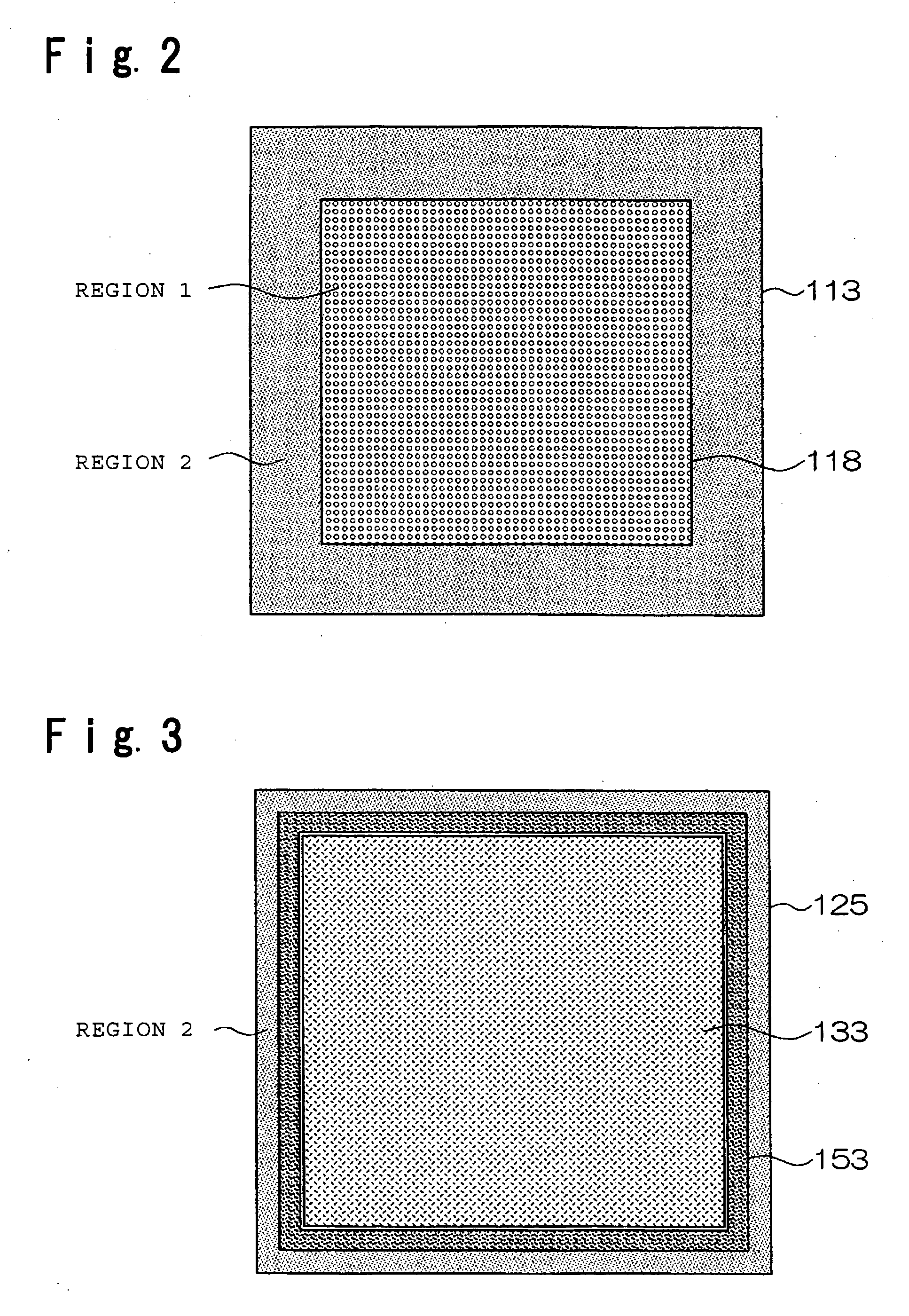
[0172] At a principal center portion of a polyphenylene sulfide film (tradename: Torelina 3030-12, manufactured by Toray Industries, Inc.) of a 200 mm square having a thickness of 12 μm, 213,280 through-holes having a diameter of 300 μm (average area per through-hole: about 0.071 mm2) were formed in a staggered arrangement so as to have a center distance of 350 μm by multiple spindle drilling, to prepare a perforated sheet 113 having a region 1 of a 150 mm square having an open area ratio of is about 67% and a region 2 having no apertures outside thereof.

[0173] Then, on a polyethylene terephthalate substrate having a thickness of approximately 100 μm and having the surface treated with a silicone releasing agent (hereinafter, the same substrate as this will be referred to as PET substrate), a dispersion of an ion exchange resin comprising repeating units based on CF2═CF2 and repeating units based on CF2═CF—OCF2CF(CF3)—OCF2CF2SO3H (ion exchange capacity: 1.1...

example 2

Preparation of Membrane

[0179] At a principal center portion of a polyphenylene sulfide film (tradename: Torelina 3030-12, manufactured by Toray Industries, Inc.) of a 200 mm square having a thickness of 12 μm, 213,280 through-holes 117 having a diameter of 300 μm (average area per through-hole: about 0.071 mm2) are formed in a staggered arrangement so as to have a center distance of 350 μm by multiple spindle drilling to prepare the region 1 of a 150 mm square with an open area ratio of about 67%, and at outside of a 162 mm square, through-holes 117 having a diameter of 300 μm are formed in a staggered arrangement so as to have a center distance of 350 μm by multiple spindle drilling, to prepare the region 3 with an open area ratio of about 67%, whereby a perforated sheet 213 is prepared in which the region 2 with no apertures has a width of 7 mm.

[0180] Then, in the same manner as in Example 1, such a perforated sheet 213 is sandwiched by PET substrates coated with the dispersion...

example 3

Preparation of Membrane

[0183] At a principal center of a film made of a perfluoroalkoxyethylene polymer (tradename: TOYOFLON PFA, manufactured by Toray Industries, Inc.) with a thickness of 25 μm, 213,280 through-holes 117 having a diameter of 300 μm (average area per through-hole: about 0.071 mm2) are formed in a staggered arrangement so as to have a center distance of 350 μm by multiple spindle drilling, to prepare the region 1 of a 150 mm square having an open area ratio of about 67%, and at outside of a 162 mm square, through-holes 117 having a diameter of 300 μm are formed in a staggered arrangement so as to have a center distance of 350 μm by the same multiple spindle drilling, to prepare the region 3 with an open area ratio of about 67%, whereby a perforated sheet 213 is prepared in which the region 2 with no apertures has a width of 7 mm in the same manner as in Example 2.

[0184] Then, in the same manner as in Example 1, such a perforated sheet 213 was sandwiched by PET su...


PUM

PropertyMeasurementUnit
thicknessaaaaaaaaaa
thicknessaaaaaaaaaa
widthaaaaaaaaaa

Abstract

The present invention provides a membrane-electrode assembly for polymer electrolyte fuel cells and a polymer electrolyte fuel cell having excellent dimensional stability and mechanical strength, and having high durability at the time of a power generation. Each of polymer electrolyte membranes (111, 211, 311) have a region 1 having proton conductivity over the entirety in the thickness direction of the membrane and a region 2 located at the outer peripheral portion of the region 1 and having a non-porous sheet disposed so that the region 2 has no proton conductivity over the entirety in the thickness direction of the membrane, and outer edges of the catalyst layers (127, 128) are disposed so as to be located in the area 2.

Description

TECHNICAL FIELD [0001] The present invention relates to a membrane-electrode assembly for polymer electrolyte fuel cells, and a polymer electrolyte fuel cell. Particularly, it relates to a membrane-electrode assembly for polymer electrolyte fuel cells, and a polymer electrolyte fuel cell having excellent dimensional stability and mechanical strength, and having high durability at the time of power generation. BACKGROUND ART [0002] Fuel cells are expected to be widely used in the future since their power generation efficiency is high, and their load to the environment is light. Particularly polymer electrolyte fuel cells are expected to be widely used for movable bodies such as automobiles, or as distributed power generation system, or cogeneration systems for home use, since their power density is high and their operating temperature is low, whereby downsizing can be carried out. [0003] A cross-sectional view of a single cell for conventional fuel cells is shown in FIG. 17. In FIG. ...

Claims


Application Information

Patent Timeline
Patent Type & Authority Applications(United States)
IPC IPC(8): H01M8/10H01M4/94H01M2/08
CPCH01M8/0271H01M8/0291Y02E60/50H01M2008/1095H01M8/1016H01M8/0289H01M8/1058H01M4/86H01M8/02
Inventor SHIMOHIRA, TETSUJIKINOSHITA, SHINJIWAKABAYASHI, HIROKAZUTERADA, ICHIROHORI, YOSHIHIRO
Owner PANASONIC CORP
Learn More