Microwave drying method of honeycomb formed bodies
a technology of honeycomb and microwave drying, which is applied in the direction of electric/magnetic/electromagnetic heating, lighting and heating apparatus, etc., can solve the problems of difficult reduction of drying speed and inability to uniformly dry the entire honeycomb formed body, and achieve the effect of reducing the difference in drying speed inside the honeycomb formed body
- Summary
- Abstract
- Description
- Claims
- Application Information
AI Technical Summary
Benefits of technology
Problems solved by technology
Method used
Image
Examples
reference example 1
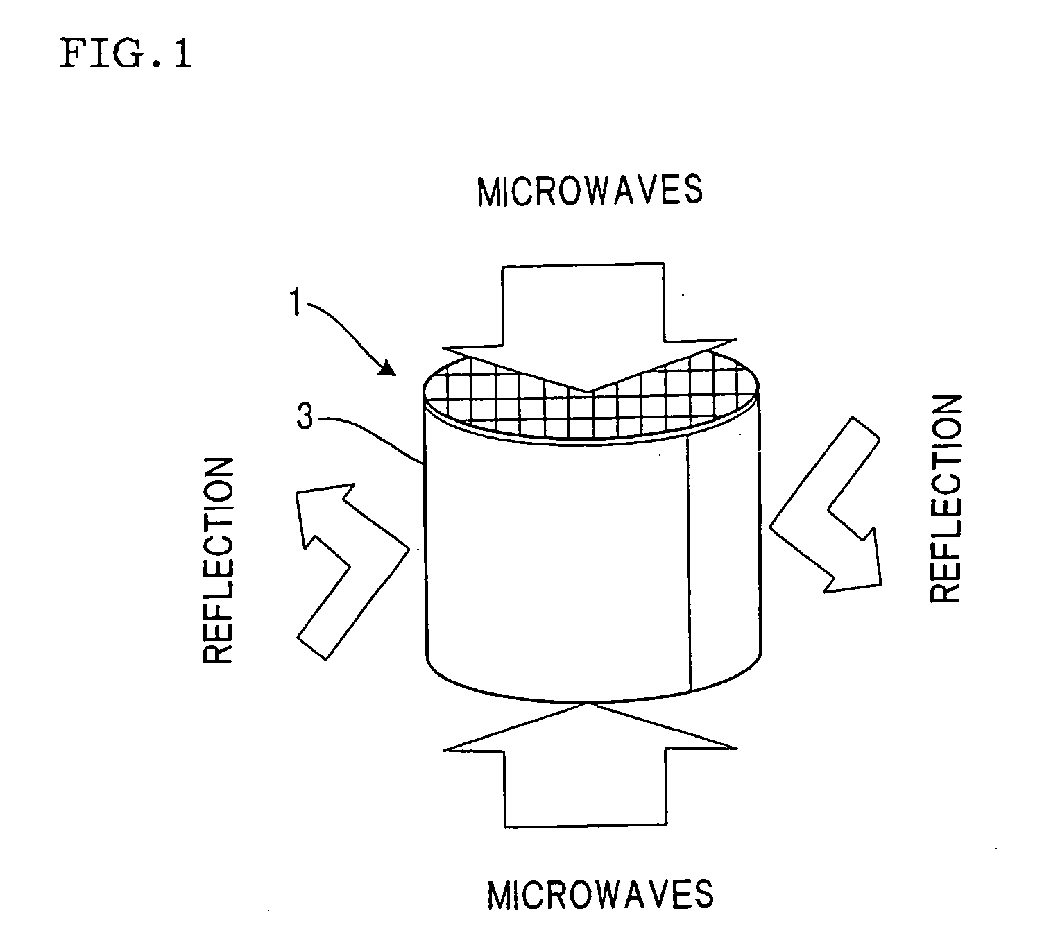
[0067] Talc, kaolin, alumina, binder, water, and the like were blended and kneaded. The resulting kneaded compound was extruded from an extruder to obtain a honeycomb formed body with a diameter of 120 mm, length of 200 mm, wall thicknesses of about 100 μm, and comprising about 300 cells per square inch (about 46 / cm2). This formed body was vertically placed (so that the cell axis is in the vertical direction) in a batch microwave drying furnace (heating efficiency: 0.5) and dried by irradiating a microwave at a frequency of 2.45 GHz for 300 seconds at an output density of 1 kW. In this example, the ratio of the microwave incident density from the vertical direction to the incident density from the horizontal direction of the honeycomb formed body is supposed to be about 1:1.
[0068] After drying, the residual water content was measured for the perimeter 11 and the core 13 of the honeycomb formed body 1 shown in FIG. 11, each from a height of 0 (bottom) to 200 (top). The results are s...
reference example 2
[0069] Talc, kaolin, alumina, binder, water, and the like were blended and kneaded. The resulting kneaded compound was extruded from an extruder to obtain a honeycomb formed body with a diameter of 120 mm, length of 220 mm, wall thicknesses of about 100 μm, and comprising about 300 cells per square inch (about 46 / cm2). This formed body was vertically placed (so that the cell axis is in the vertical direction) in a batch microwave drying furnace (heating efficiency: 0.5) and dried by irradiating microwaves at a frequency of 2.45 GHz for 600 seconds at an output density of 0.5 kW / kg. In this example, the ratio of the microwave incident density from the vertical direction to the incident density from the horizontal direction of the honeycomb formed body is supposed to be about 1:1. After drying, the residual water content was measured for the perimeter 11 and the core 13 of the honeycomb formed body 1 shown in FIG. 11, each from a height of 160 (bottom) to 220 (top).
reference example 3
[0070] A formed body prepared in the same manner as in Reference Example 2 was vertically placed (so that the cell axis is in the vertical direction) in a batch microwave drying furnace (heating efficiency: 0.5) and dried by irradiating microwaves at a frequency of 2.45 GHz for 60 seconds at an output density of 5 kW / kg. In this example, the ratio of the microwave incident density from the vertical direction to the incident density from the horizontal direction of the honeycomb formed body is supposed to be about 1:1. After drying, the residual water content was measured in the same manner as in Reference Example 2. The results are shown in FIG. 14.
[0071] It can be seen from FIG. 13 and FIG. 14 that the difference in the residual water content in the vertical direction, i.e., the difference in the drying speed in the vertical direction, is smaller in Reference Example 3 with a larger microwave output density of 5 kW / kg than in Reference Example 2 with a smaller power microwave outp...
PUM
| Property | Measurement | Unit |
|---|---|---|
| Length | aaaaa | aaaaa |
| Frequency | aaaaa | aaaaa |
| Length | aaaaa | aaaaa |
Abstract
Description
Claims
Application Information
 - R&D
- Intellectual Property
- Life Sciences
- Materials
- Tech Scout
- Unparalleled Data Quality
- Higher Quality Content
- 60% Fewer Hallucinations
Browse by: Latest US Patents, China's latest patents, Technical Efficacy Thesaurus, Application Domain, Technology Topic, Popular Technical Reports.
© 2025 PatSnap. All rights reserved.Legal|Privacy policy|Modern Slavery Act Transparency Statement|Sitemap|About US| Contact US: help@patsnap.com


