
Organic electroluminescence display and method of manufacturing the same

Active Publication Date: 2005-12-15
SAMSUNG DISPLAY CO LTD
View PDF4 Cites 33 Cited by
  • Summary
  • Abstract
  • Description
  • Claims
  • Application Information

AI Technical Summary

Benefits of technology

[0012] It is further an object of the present invention to provide an organic electroluminescence device with improved interfacial adhesion between a substrate and a sealant and improved lifetime characteristics, and a method of manufacturing the same.

Problems solved by technology

Organic electroluminescence devices are deteriorated by moisture.
However, the method of loading the desiccant in powder form into the grooves is complicated and raises costs.
In addition, the overall thickness of a substrate becomes thick, and the substrate used for passivation is not transparent so that it cannot be used for front emission.
A metal can used for passivation is structurally rigid, whereas an etched glass is structurally fragile and is easily damaged by external impacts.
When passivation is achieved using the film type desiccant, the permeation of moisture cannot be completely prevented, and the structure is likely to be broken by external impacts in a manufacturing process or in use.
Therefore, passivation using the desiccant film is not suitable for mass production due to poor durability and low reliability.
However, the organic electroluminescence display device is considerably thick due to the structure of the sealing container.
In addition, even though the desiccant remains in a solid state after absorbing moisture, it is opaque and unsuitable for a front emission organic electroluminescence device.
In addition, as described above, expensive materials and the complicated manufacturing processes increase the overall costs.
However, according to the conventional method, circumferential contamination occurs when coating the transparent moisture-absorbing material, and outgassing from solvents occurs during the calcinating process.
As a result, the interfacial adhesion between the sealant and the glass substrate greatly decreases, thereby fatally affecting the lifetime characteristics of the device.

Method used


Image

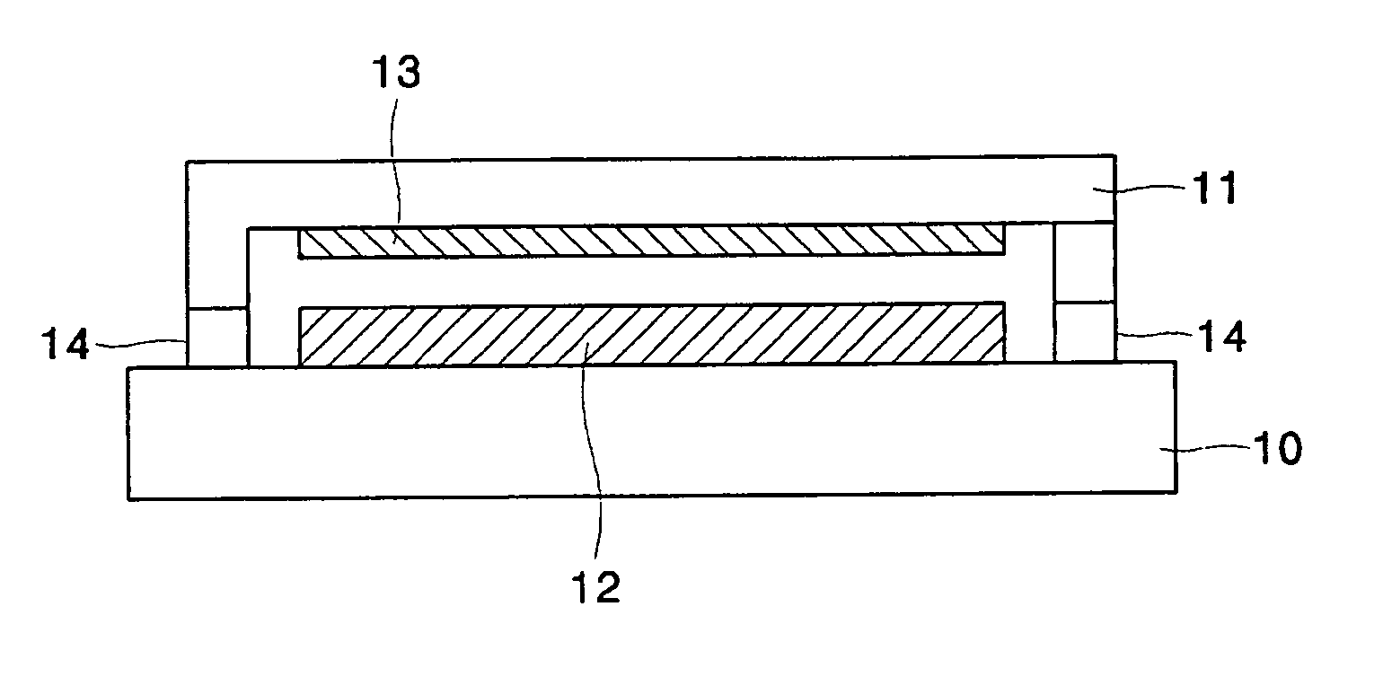
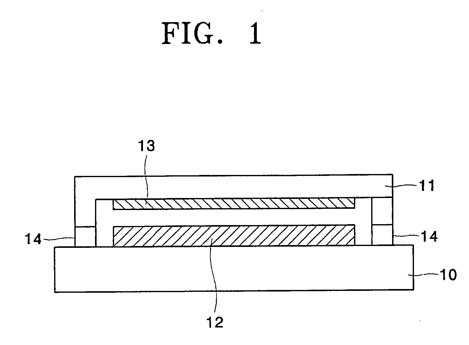
  • Organic electroluminescence display and method of manufacturing the same
  • Organic electroluminescence display and method of manufacturing the same

Examples


example 1

[0038] A nitric acid was added to 95 g of ethanol to adjust pH to 2.5 g of CaO powder was added to the solution and mixed for 3 hours or longer to obtain a mixture in sol state.

[0039] The mixture in sol state was spin-coated on a soda glass substrate at 180 rpm for 120 seconds and dried in a drying oven for about 2 minutes to remove the unvaporized solvent. The resulting structure was thermally treated at about 250° C. for 30 minutes to form a transparent, nano-porous CaO layer having a thickness of 3.5 μm.

[0040] A plasma treatment was performed on a region of the soda glass substrate, in which a sealant was later applied, in an Ar gas atmosphere after the transparent, nano-porous CaO layer was formed. The plasma treatment was performed at a pressure of about 5×10⁻⁵ torr, an Ar flow rate of about 150-250 sccm, and a RF power of about 300W for about 5 minutes.

[0041] Subsequently, an epoxy resin as a sealant was applied to at least one of the plasma-treated soda glass substrate and...


PUM


Abstract

A method of manufacturing an organic electroluminescence device whereby an encapsulating layer is formed by coating an encapsulating substrate with an encapsulating layer-forming composition and thermally processing the encapsulating substrate. A plasma treatment is performed on the encapsulating substrate having the encapsulating layer. A sealant is applied to at least one of the plasma treated encapsulating substrate and a substrate on which an organic electroluminescent unit including a first electrode, an organic layer, and a second electrode, which are sequentially stacked, is deposited. The sealing substrate and the substrate on which the organic electroluminescent unit is deposited are combined. Contaminants generated around the encapsulating layer and generated in the thermal process can be effectively removed by the cleaning process using plasma. Therefore, the interfacial adhesion between the sealant and the substrate is greatly improved, thereby preventing permeation of external air, moisture, etc., into the device.

Description

CLAIM OF PRIORITY [0001] This application claims the benefit of Korean Patent Application No. 10-2004-0042224, filed on Jun. 9, 2004, in the Korean Intellectual Property Office, the disclosure of which is incorporated herein in its entirety by reference. BACKGROUND OF THE INVENTION [0002] 1. Field of the Invention [0003] The present invention relates to an organic electroluminescence device, and more particularly, to an organic electroluminescence device with improved interfacial adhesion between a substrate and a sealant. [0004] 2. Description of the Related Art [0005] Organic electroluminescence devices are deteriorated by moisture. Thus, a passivation structure for preventing moisture permeation is required. [0006] In a conventional sealing structure, a metal can or a glass plate is processed into a cap having grooves, and a moisture-absorbing desiccant in powder form is loaded into the grooves. Alternatively, a film type desiccant is attached using a double-sided tape. [0007] Ho...

Claims


Application Information

Patent Timeline
IPC IPC(8): H05B33/04G09F9/30H01J9/26H01L27/32H01L51/50H01L51/52H05B33/10H05B33/14
CPCH01L51/5237H10K59/874H10K59/8722H05B33/10H05B33/04B82Y30/00H10K50/846H10K50/8426
Inventor CHOI, DONG-SOOSONG, SEUNG-YONGPARK, JIN-WOO
Owner SAMSUNG DISPLAY CO LTD
Learn More