Methods and composition for cleaning and passivating fuel cell systems
a fuel cell and passivating technology, applied in the direction of detergent compounding agents, flush cleaning, lighting and heating apparatus, etc., can solve the problem that the use of corrosion inhibitors may not be feasible in these systems
- Summary
- Abstract
- Description
- Claims
- Application Information
AI Technical Summary
Benefits of technology
Problems solved by technology
Method used
Image
Examples
example 1
Cleaner-Passivator Composition
[0031]
TABLE 1Composition of cleaner-passivator for Example 1ComponentFunctionWeight %DI WaterSolvent88.843% Citric acidComplexing agent4.625% NaOH, 50%pH adjusting agent5.842% Silquest ® Y-5560 SilaneCorrosion inhibitor0.08%Sodium SilicateCorrosion inhibitor0.21%Potassium PyrophosphateComplexing agent and0.05%corrosion inhibitorSodium TolytriazoleCorrosion inhibitor0.05%Sodium NitrateCorrosion inhibitor 0.2%Pluronic L-61Surfactant and antifoam agent 0.1%Total 100%
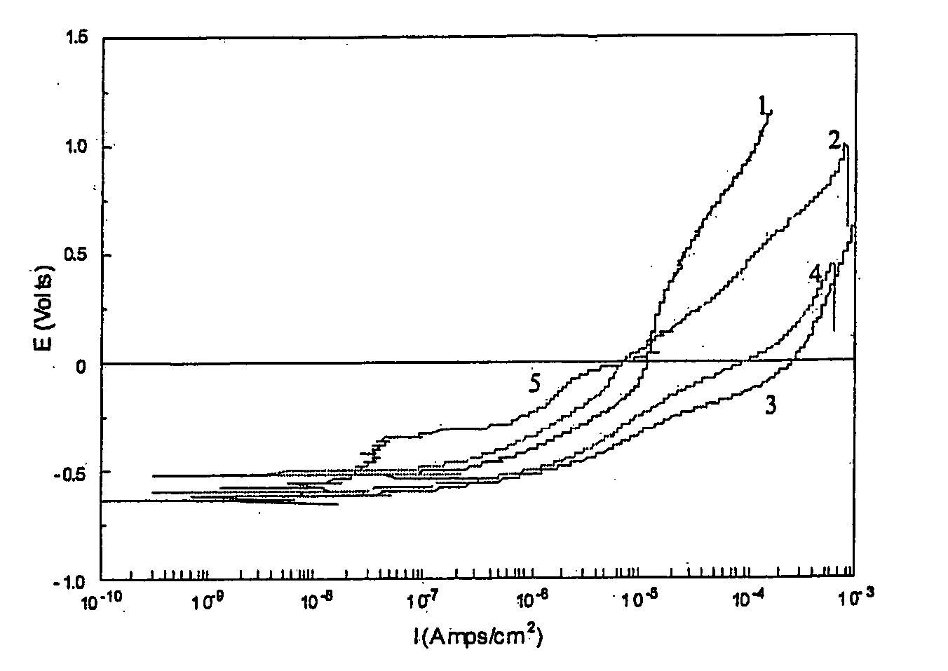
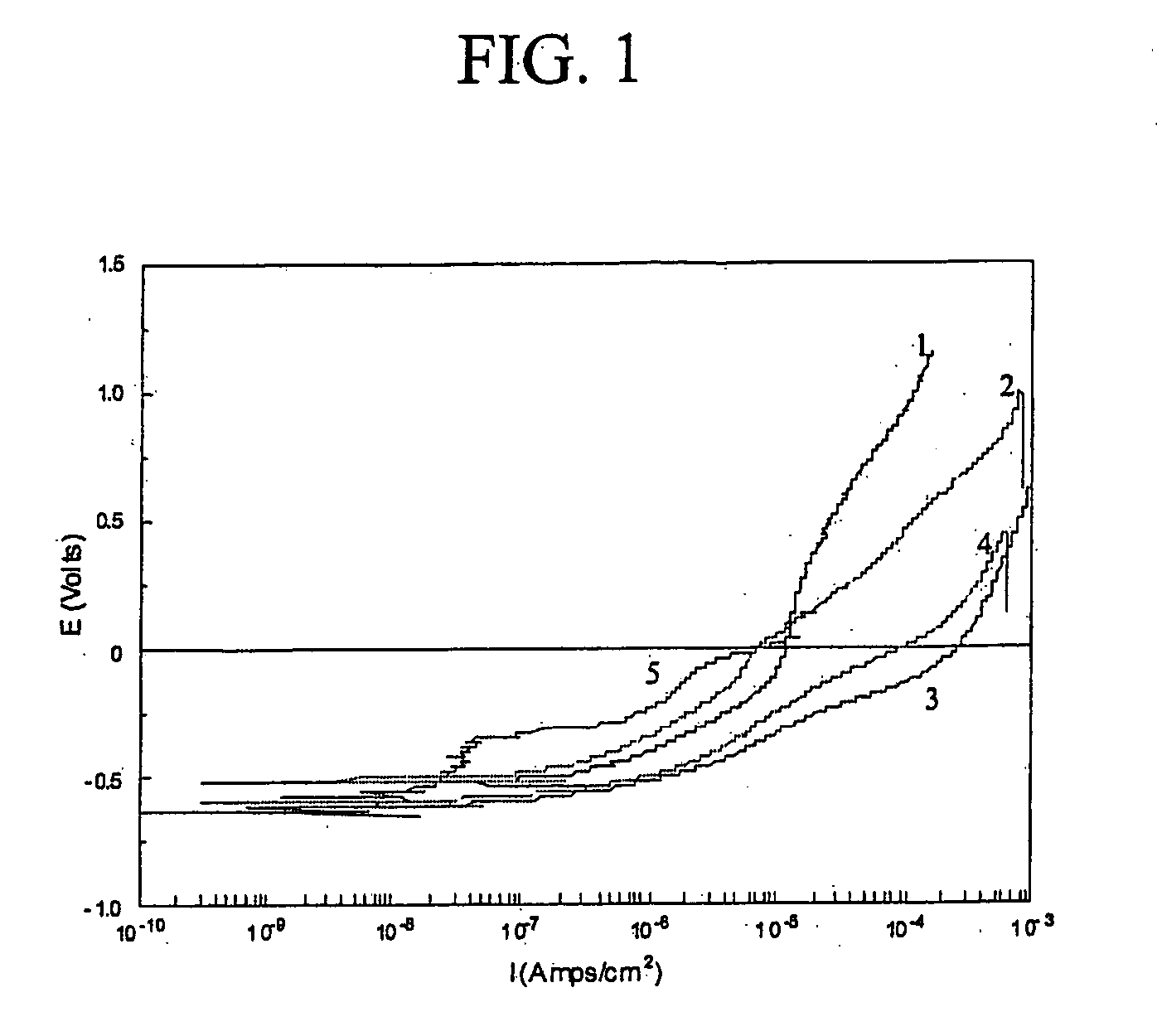
[0032] In this example, the concentrated cleaner-passivator was diluted 10-fold (270 ml deionized (DI) water +30 ml cleaner-passivator). The samples used to mimic the components typically employed in fuel cell coolant systems were two cast aluminum coupons, two brass coupons, two stainless steel (SS316) coupons, one brazed aluminum coupon, one silicone gasket, and two Viton O-rings. The total surface area of the samples was 194 square centimeters and the samples were electrically connected to ...
example 2
Alternate Cleaner-Passivator System
[0034]
TABLE 3Cleaner-Passivator CompositionComponentFunctionWeight %DI WaterSolvent88.743% Citric acidComplexing agent4.625% NaOH, 50%pH adjusting agent5.842% Silquest ® Y-5560 SilaneCorrosion inhibitor0.08%Sodium silicateCorrosion inhibitor0.21%Potassium PyrophosphateComplexing agent and0.05%corrosion inhibitorSodium TolytriazoleCorrosion inhibitor0.05%Sodium NitrateCorrosion inhibitor 0.2%Pluronic L-61Surfactant and antifoam agent 0.2%Total 100%
[0035] The cleaner-passivator treatment of Example 2 was identical to that of Example 1, except that the amount of surfactant / antifoam was doubled. The samples used included one cast aluminum coupon, one brass pipe section, one stainless steel (SS316) coupon, one brazed aluminum coupon, one silicone gasket, and two Viton O-rings. The total surface area of the samples was 120 square centimeters. The samples were electrically connected to each other. Two sets of samples were put into separate glass jars wit...
example 3
Alternative Cleaner-Passivator
[0038]
TABLE 5Cleaner-Passivator CompositionComponentFunctionWeight %DI WaterSolvent88.773% Citric acidComplexing agent4.624%NaOH, 50%pH adjusting agent5.813%PPG-2000 (polypropyleneAntifoam0.002%glycol)Sodium silicateCorrosion inhibitor 0.07%n-propanolSolvent0.018%Potassium PyrophosphateComplexing agent and 0.05%corrosion inhibitorSodium TolytriazoleCorrosion inhibitor 0.05%Tomadol 25-12(ethoxylatedSurfactant 0.6%alcohol)Total 100%
[0039] A test procedure similar to the one used in Example 1 was used. One difference was that the cleaning-passivating step was carried out at a room temperature, e.g., at about 22° C. in these tests. The test samples were identical (in terms of quantity and kind) to the ones used in Example 2.
TABLE 6Results for the cleaner-passivator of Example 3RinseRinseNo. -No. -BlankTestTemper-TimeBlankTestConductivityConductivityature0min009.31μS / cm11.08mS / c21.5° C.20min0013.46μS / cm11.16mS / cm20.7° C.40min0014.53μS / cm10.95mS / cm22.7° C...
PUM
| Property | Measurement | Unit |
|---|---|---|
| pH | aaaaa | aaaaa |
| pH | aaaaa | aaaaa |
| pH | aaaaa | aaaaa |
Abstract
Description
Claims
Application Information
 - R&D
- Intellectual Property
- Life Sciences
- Materials
- Tech Scout
- Unparalleled Data Quality
- Higher Quality Content
- 60% Fewer Hallucinations
Browse by: Latest US Patents, China's latest patents, Technical Efficacy Thesaurus, Application Domain, Technology Topic, Popular Technical Reports.
© 2025 PatSnap. All rights reserved.Legal|Privacy policy|Modern Slavery Act Transparency Statement|Sitemap|About US| Contact US: help@patsnap.com


