
Optical information recording medium, manufacturing method of the same and optical information recording and reproducing apparatus

a manufacturing method and optical information technology, applied in mechanical recording, instruments, transportation and packaging, etc., can solve the problems of increasing the storage capacity of the current 23.3 gb optical disc for the blue laser, becoming more difficult than ever to develop inexpensive laser diodes or semiconductor lasers, and achieving low power consumption , the effect of large storage capacity of the optical information recording medium

Inactive Publication Date: 2005-09-29
HITACHI LTD
View PDF12 Cites 20 Cited by
  • Summary
  • Abstract
  • Description
  • Claims
  • Application Information

AI Technical Summary

Benefits of technology

[0016] The present invention is especially effective for increasing the capacity of an optical information recording medium on which information is recorded with the irradiation with a short-wavelength laser beam having a wavelength of 405 nm or less.
[0017] As will be described in the following embodiments, the effects of the present invention were confirmed regarding super-resolution layers formed of various oxides (Fe2O3, NiO, CoO, ZnO, Cr2O3, etc.), super-resolution layers formed of a mixture of Fe2O3 and one selected from Cr2O3, CeO2, MnO, ZnO, NiO, CoO, MgO, CuO, BaO, Y2O3 and CdO, super-resolution layers formed of a mixture of Fe2O3, SiO2 and TiO2, and super-resolution layers formed of ZnS—ZnSe, GaN—InN, ZnS, GaN and ZnSe.
[0026] The optical information recording medium in accordance with the present invention is equipped with a super-resolution layer having a band gap close to the energy of the laser beam applied to the medium. Since changes in the refractive index and the extinction coefficient caused by laser excitation are remarkable, significant changes in the refractive index and extinction coefficient can be achieved even with low laser output. Therefore, large storage capacity of the optical information recording medium can be attained with low power consumption of an optical information recording and reproducing apparatus.
[0027] In the optical information recording medium of the present invention, the change in transmittance caused by heating is remarkable, by which significant change in transmittance can be achieved even when the output of the laser is low and the temperature of the heated part of the medium is low. Therefore, strong super-resolution effect in an optical disc can be achieved and thereby an optical information recording medium attaining high storage capacity with low power consumption can be obtained.

Problems solved by technology

However, it is thought to be difficult to further increase the storage capacity of the current 23.3 GB optical disc for the blue laser by use of conventional methods like shortening the wavelength, increasing NA (Numerical Aperture) of the lens, etc.
Further, it becomes more difficult than ever to develop laser diodes or semiconductor lasers that are inexpensive and capable of emitting ultraviolet light stably.

Method used


Image

  • Optical information recording medium, manufacturing method of the same and optical information recording and reproducing apparatus
  • Optical information recording medium, manufacturing method of the same and optical information recording and reproducing apparatus
  • Optical information recording medium, manufacturing method of the same and optical information recording and reproducing apparatus

Examples


embodiment 1

[0074]FIG. 1 is a schematic cross-sectional view of an optical disc in accordance with an embodiment of the present invention. In FIG. 1, a reference numeral “1” denotes a substrate, “2” denotes a reflecting layer, “3”, “5” and “7” denote protective layers, “4” denotes an optical information recording layer, “6” denotes a super-resolution layer, “8” denotes a cover layer, “9” denotes a groove, and “10” denotes a land. A laser beam for information read / write is applied to the optical disc from its cover layer side to focus on the surface of the substrate, by which information can be recorded on the optical information recording layer 4 as well as reproducing the recorded information.

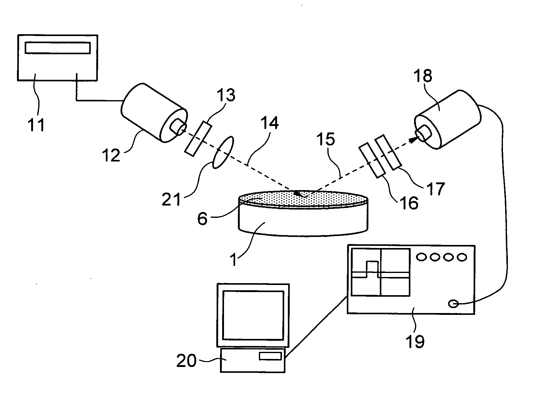
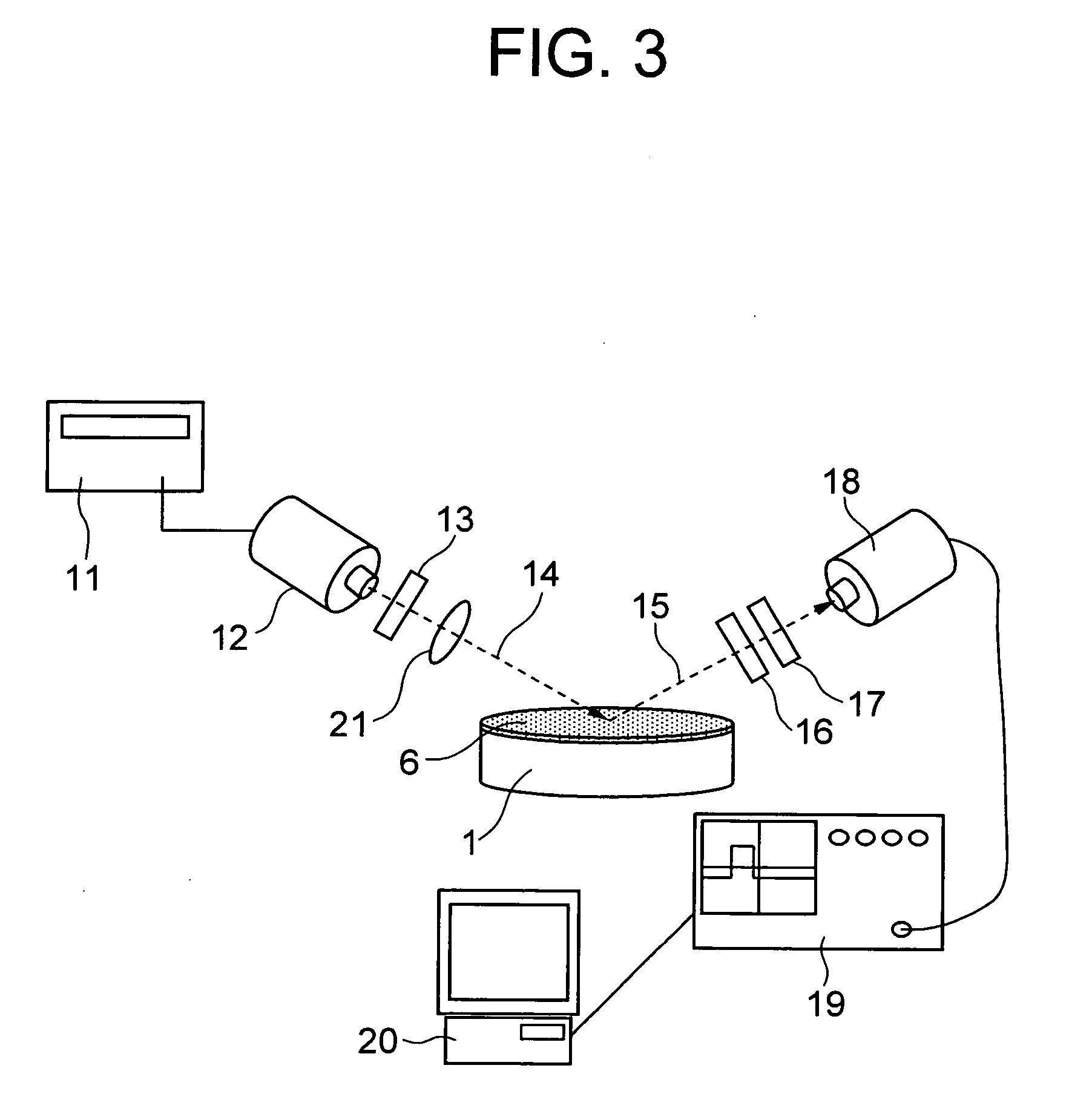
[0075] A laser beam having a wavelength of 405 nm, emitted by an InGaN-based compound semiconductor laser as the light source, was used for the experiment. While the semiconductor laser generally emits the laser beam continuously, a pulsed laser beam (pulsed by a pulse generator according to recording in...

embodiment 2

[0115] Similar examination was carried out for other transition metal oxides. The following Table 2 shows the composition of super-resolution layers and oxygen gas flow ratios (in the whole gas) which were examined, together with the band gap energy Eg, the band gap wavelength λg corresponding to the band gap energy Eg, the difference (λ−λg) between the measurement wavelength λ and the band gap wavelength λg, the specific transmittance difference ΔT at the wavelength 405 nm, and the C / N ratio obtained by producing the optical disc shown in FIG. 1 and reading 0.05 μm pits. The oxygen gas flow ratio denotes the ratio of an oxygen gas flow (flow of oxygen gas) to a total gas flow (flow of the whole gas as a mixture of oxygen gas and Ag gas as the main deposition gas) in units %.

TABLE 2SUPER-RESOLUTIONOXYGEN FLOWSAMPLELAYER COMPOSITIONRATIO IN GASEgλgλ−λgΔTC / NNO.(MOLAR RATIO)(%)(eV)(nm)(nm)(%)(dB)10Fe2O302.704595412.83511Fe2O352.714575213.73612Fe2O3102.694615612.03413Fe2O3202.70459541...

embodiment 3

[0141] Another embodiment of an optical disc in accordance with the present invention will be described below. FIG. 24 is a schematic cross-sectional view showing an optical disc of this embodiment. In FIG. 24, a reference numeral “201” denotes a substrate, “202” denotes a reflecting layer, “203” denotes a protective layer, “204” denotes a super-resolution layer, “205” denotes an adhesive layer, “206” denotes a cover layer, and “209” denotes record pits. In the present invention, an Fe2O3—Ga2O3 thin layer was used as the super-resolution layer 204. The Fe2O3—Ga2O3 thin layer may be doped with heat-absorbing material such as Bi.

[0142] In this embodiment, optical discs were produced by depositing the thin layer materials on optical discs having a substrate 201 like the one shown in FIG. 24 on which a random signal pattern has been formed or on optical disc substrates exclusively for the C / N ratio test on which record pits and spaces have been formed at even intervals. In the optical ...


PUM

PropertyMeasurementUnit
transmittanceaaaaaaaaaa
thicknessaaaaaaaaaa
thicknessaaaaaaaaaa

Abstract

An optical information recording medium includes at least a reflecting layer, an optical information recording layer, a super-resolution layer and a protective layer. The super-resolution layer is a thin layer whose an optical constant changes nonlinearly due to a red shift of its band gap, and made of solid solution, compound or mixture of metal oxides containing two or more types of metal ions of the same valence. Ion radius unconformity ΔR=|(RMi−RMj) / RMj| between ion radii RMi and RMj of two types of metal ions Mi and Mj arbitrarily selected from the two or more types of metal ions is 8% or less. The difference ΔE=Eg−E between band gap energy Eg of the mixture of the metal oxides and energy E corresponding to a wavelength of the laser beam is a more 0.4 or less 1.4 eV.

Description

BACKGROUND OF THE INVENTION [0001] The present invention relates to a high-capacity optical information recording medium, a manufacturing method thereof, and an optical information recording and reproducing apparatus. [0002] The progress of information-oriented society in recent years using optical communications has been requiring the construction of a communication system capable of communicating a large amount information at high speed. Optical devices essential for deploying such high-capacity high-speed optical communication include optical information recording media for storing high-volume optical information. Further, with the improvement of quality of video images (e.g. television pictures) by digitization, high definition technology, etc., the development of high-capacity optical information recording media, capable of maintaining the video images in high quality states and allowing long-duration recording, is an urgent necessity. [0003] As the optical information recordin...

Claims


Application Information

Patent Timeline
Patent Type & Authority Applications(United States)
IPC IPC(8): G11B7/24G11B7/24065G11B7/26
CPCG11B7/24G11B7/243Y10T428/21G11B2007/24308G11B2007/2432G11B2007/24304
Inventor YAMAMOTO, HIROKIMOMOSE, HIDETOSAWAI, YUUICHINAITO, TAKASHI
Owner HITACHI LTD
Learn More