
Structure and process to fabricate lead overlay (LOL) on the bottom spin valve

a technology of lead overlay and bottom spin valve, which is applied in the field of fabrication of giant magnetoresistive (gmr) magnetic field sensor of the bottom spin valve, can solve the problems of narrow trackwidth design, reduced signal amplitude and sensor stability, and almost impossible to avoid shorting between lol edges, etc., to enhance the signal strength produced by the sensor and reduce resistance.

Inactive Publication Date: 2005-02-24
HEADWAY TECH INC
View PDF13 Cites 7 Cited by
  • Summary
  • Abstract
  • Description
  • Claims
  • Application Information

AI Technical Summary

Benefits of technology

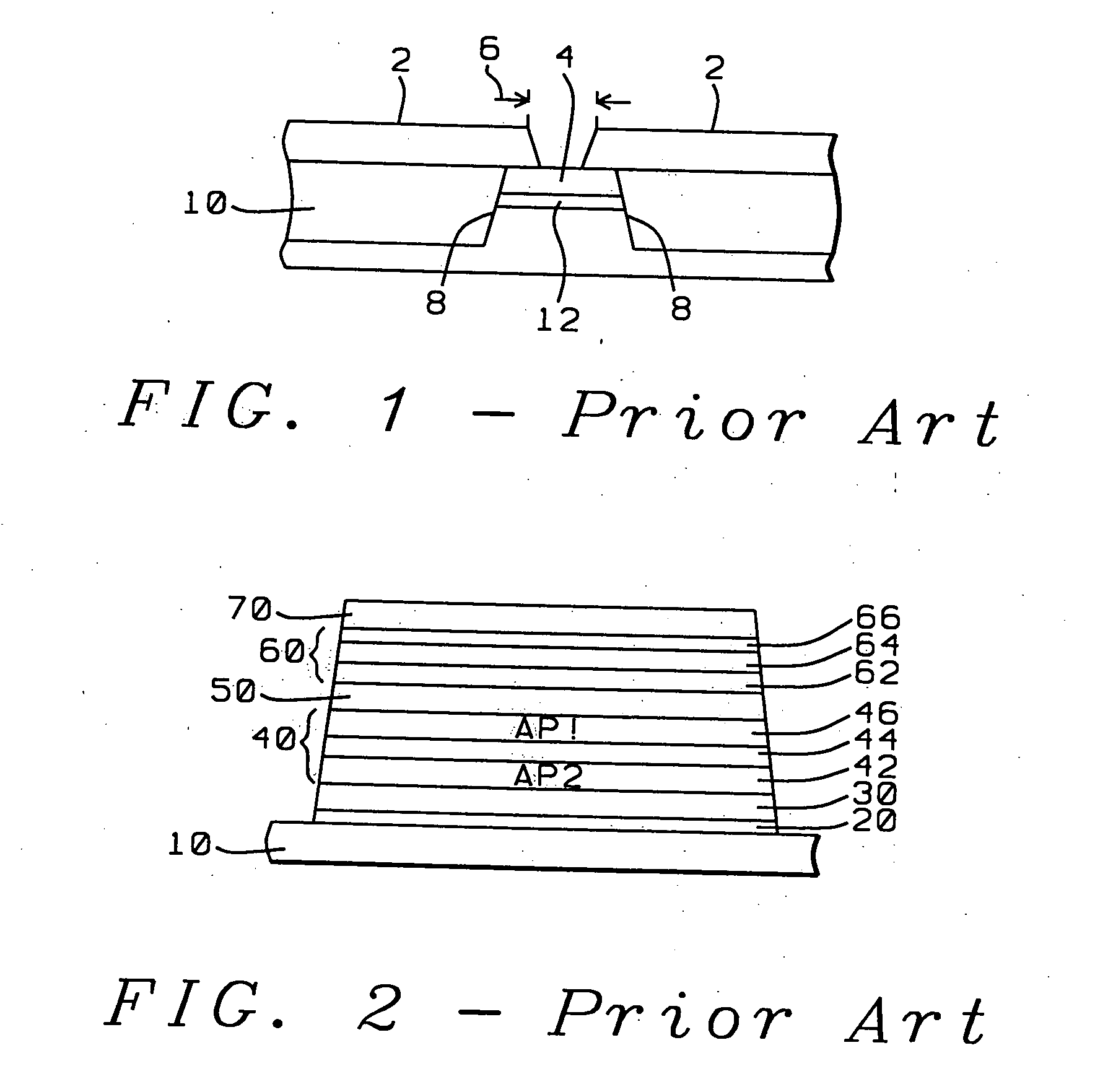
[0010] It is a first object of the present invention to provide a high signal output, magnetically stable, longitudinally hard biased bottom spin valve (BSV) GMR sensor capable of reading high area density magnetic recordings of densities exceeding 45 Gb / in (gigabits per square inch).
[0011] It is a second object of the present invention to provide such a BSV GMR sensor having a LOL configuration that is structurally stable and resistant to smearing and electromigration.
[0012] It is a third object of the present invention to provide such a LOL configured sensor with improved electrical contact between the lead layer and capping layer.
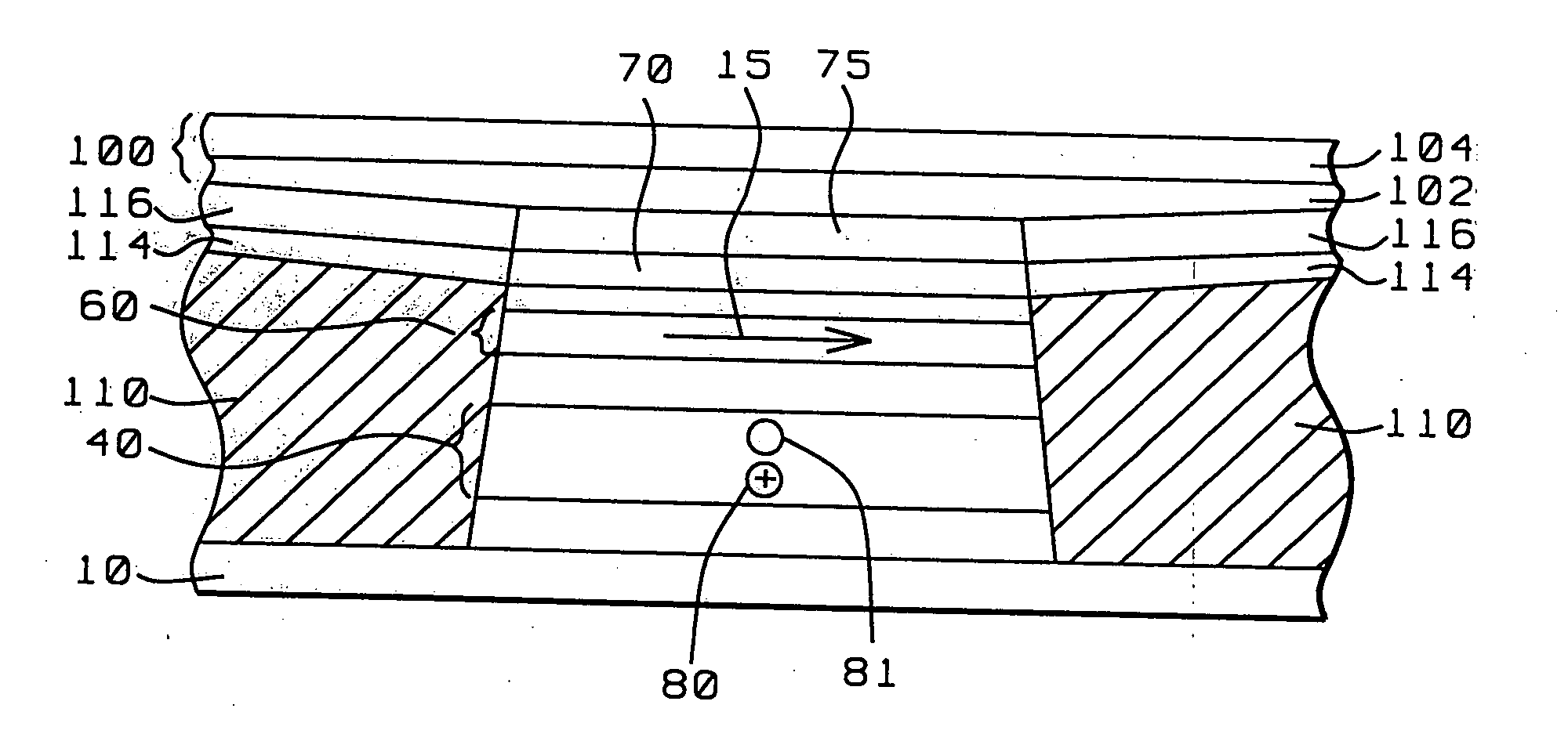
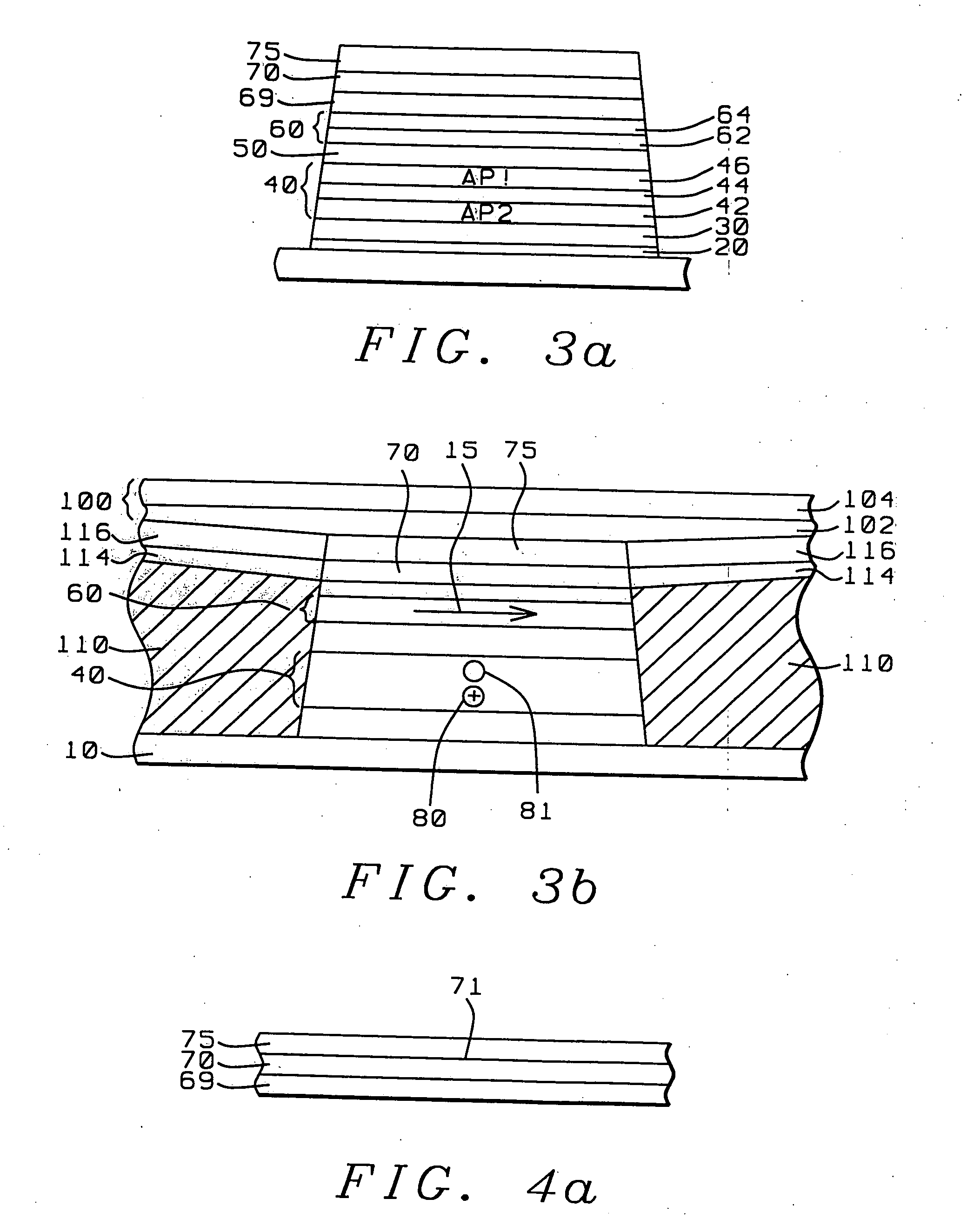
[0014] The objects of the present invention will be achieved by the use of a novel LOL layer in conjunction with a novel barrier layer and capping layer and is described briefly with reference to FIGS. 3a and 3b as follows. The capping layer consists of a usual 20-30 angstroms Ta capping layer (70) over which a novel Au layer (75) 100 angstroms thick is deposited in situ. The Au / Ta layer has been deposited over a novel Ru barrier layer (69), which will protect the free layer (60) beneath it from Au interdiffusion during processing. A further advantage of the Ta layer (70) is that it can be grown in a low resistance phase.
[0015] Subsequent to stack patterning but prior to the formation of a longitudinal hard bias layer (110) of FIG. 3b, the sensor stack is given a first pinned layer anneal, wherein the Au layer protects the Ta layer from oxidation. A Ta (125 angstroms) / Au (350 angstroms) LOL layer (100) is then deposited as a blanket layer over the (unoxidized) Ta capping layer (70). A narrow physical trackwidth of width less than 0.15 microns is then formed through said LOL layer by applying a two-step reactive ion etch (RIE), wherein the first step consists of application of a CF4 RIE through a photoresist pattern to remove the 125 angstrom upper portion of the Ta layer, whereupon a second step consists of using the now patterned Ta layer as a mask for an Ar / O2 plasma RIE etch. An additional advantage of the Ar / O2 plasma etch is that the O2 component oxidizes the upper Ta portion of the LOL to form a specularly reflecting layer that enhances the signal strength produced by the sensor. The unoxidized Ta layer of the capping layer provides electrical contact between the LOL and the sensor stack. The sensor so fabricated has an effective magnetic trackwidth of approximately 0.2 microns.

Problems solved by technology

Unfortunately, narrow trackwidth designs tend to have reductions in both signal amplitude and sensor stability.
In a very narrow sensor with a very narrow stack formation, the portion of the free layer pinned by the bias layer constitutes a dead zone as far as free layer response is concerned and so the strength of the bias layer may actually contribute to sensor instability rather than reduce it.
When very narrow physical trackwidths are being formed it is almost impossible to avoid shorting between the LOL edges.

Method used


Image

  • Structure and process to fabricate lead overlay (LOL) on the bottom spin valve
  • Structure and process to fabricate lead overlay (LOL) on the bottom spin valve
  • Structure and process to fabricate lead overlay (LOL) on the bottom spin valve

Examples


Embodiment Construction

[0022] Referring first to FIG. 3a there is shown a schematic cross-sectional view through an ABS plane of a bottom spin valve (BSV) GMR sensor stack subsequent to a first annealing process but before the formation of a contiguous longitudinal hard bias layer and blanket LOL layer. The stack is formed in accord with the preferred embodiment of the present invention.

[0023] Moving vertically upward in the stack structure, on the substrate (10) there is first seen a seed layer (20), which is typically a structure enhancing layer of NiCr and which is typically formed to a thickness of between approximately 50 and 65 angstroms, with approximately 60 angstroms being preferred. On the seed layer there is then formed a pinning layer (30) of antiferromagnetic material, typically MnPt, formed to a thickness of between approximately 100 and 150 angstroms, with approximately 120 angstroms being preferred. On the pinning layer there is then formed a pinned layer (40), which, in this embodiment, ...


PUM

PropertyMeasurementUnit
Lengthaaaaaaaaaa
Lengthaaaaaaaaaa
Thicknessaaaaaaaaaa

Abstract

A method for fabricating a longitudinally hard biased, bottom spin valve GMR sensor with a lead overlay (LOL) conducting lead configuration and a narrow effective trackwidth. The advantageous properties of the sensor are obtained by providing two novel barrier layers, one of which prevents oxidation of and Au diffusion into the free layer during annealing and etching and the other of which prevents oxidation of the capping layer during annealing so as to allow good electrical contact between the lead and the sensor stack.

Description

RELATED PATENT APPLICATION [0001] This application is related to Docket No. HT00-026, Ser. No. 09 / 147,284, filing date (Dec. 26, 2000), assigned to the same assignee as the current invention.BACKGROUND OF THE INVENTION [0002] 1. Field of the Invention [0003] This invention relates generally to the fabrication of a giant magnetoresistive (GMR) magnetic field sensor of the bottom spin-valve (BSV) type and more specifically to methods for eliminating undesirable oxidations and diffusions during annealing and patterning when forming lead overlay (LOL) type lead layers. [0004] 2. Description of the Related Art [0005] Magnetic read heads whose sensors make use of the giant magnetoresistive effect (GMR) in the bottom spin-valve configuration (BSV) are being increasingly required to read information recorded on magnetic media at ultra-high area densities (e.g. >45 Gb / in2). To be capable of reading such area densities, the sensor must be able to resolve extremely high linear bit densities...

Claims


Application Information

Patent Timeline
IPC IPC(8): G11B5/39
CPCB82Y10/00B82Y25/00G11B5/3903G11B2005/3996Y10T29/49048Y10T29/49052Y10T29/49041Y10T29/49032Y10T29/49034Y10T29/49044
Inventor HORNG, CHENG T.CHEN, MAO-MINCHIEN, CHEN-JUNGHAN, CHERNG-CHYITONG, RU-YINGTORNG, CHYU-JIUHWANG, HUI-CHUAN
Owner HEADWAY TECH INC
Learn More