Semiconductor device and manufacturing method thereof
a technology of semiconductors and semiconductors, applied in the direction of identification means, instruments, optics, etc., can solve the problems of complex process and non-normal operation of display panels, and achieve the effect of low resistance of wires
- Summary
- Abstract
- Description
- Claims
- Application Information
AI Technical Summary
Benefits of technology
Problems solved by technology
Method used
Image
Examples
embodiment 1
[0052]Here, a bottom gate semiconductor device is described.
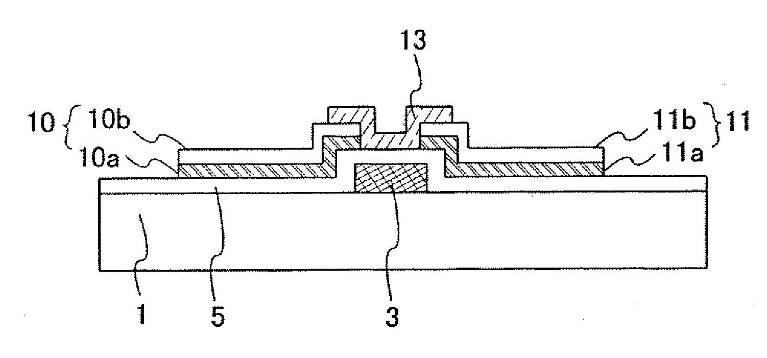
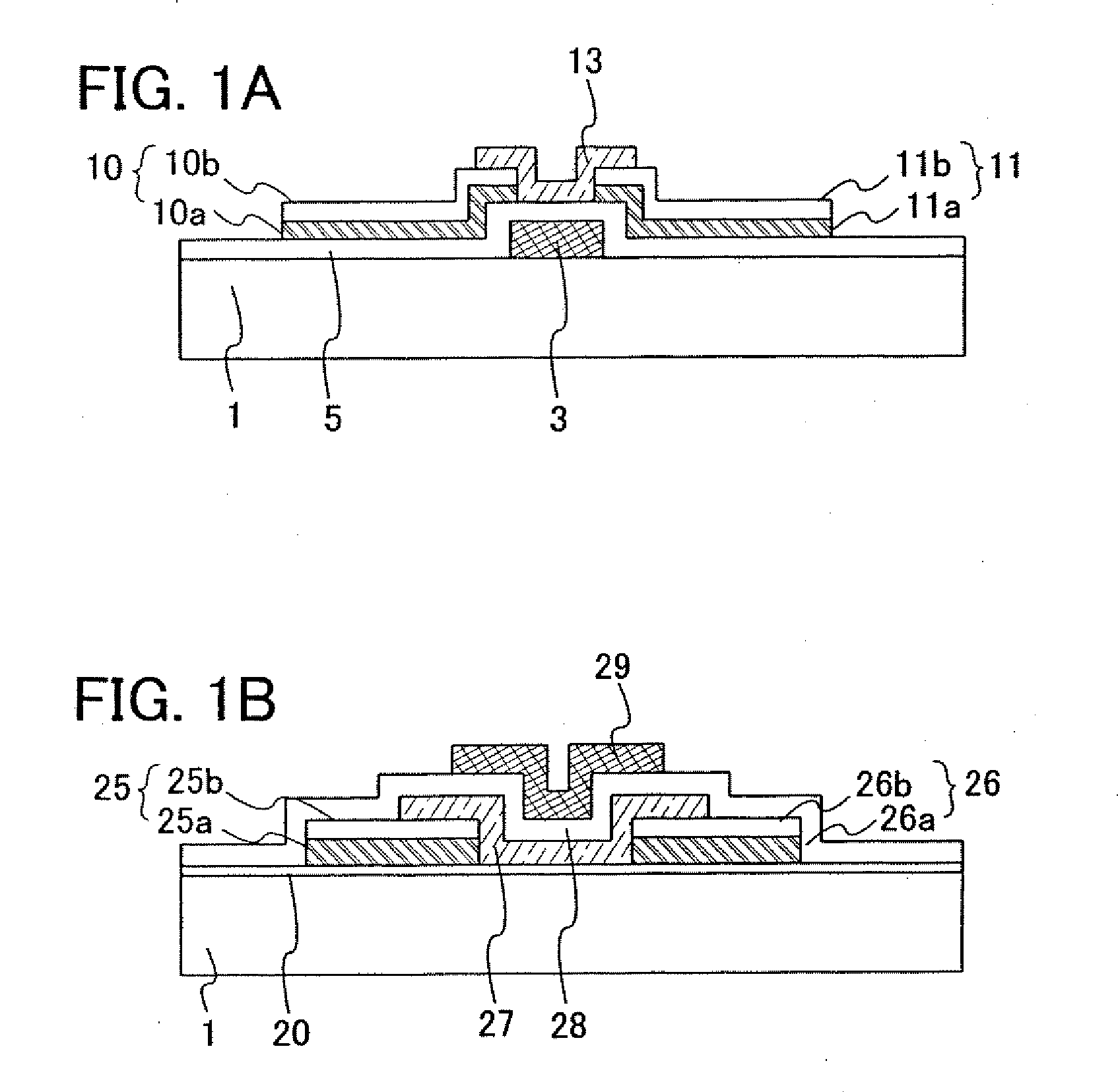
[0053]FIG. 1A is a cross-sectional view in which one example of the embodiment of this invention is shown. In FIG. 1A, numeral reference 1 denotes a substrate, 3 denotes a gate electrode, 5 denotes a gate insulating film, 10 denotes a source electrode, 10a denotes a first conductive film, 10b denotes a second conductive film, 11 denotes a drain electrode, 11a denotes a first conductive film, 11b denotes a second conductive film, and 13 denotes a semiconductor film. An insulating film for passivation or planarization may be formed over the semiconductor film 13.
[0054]The gate electrode 3 is formed over the substrate 1, the gate insulating film 5 is formed over the gate electrode 3, and the source electrode 10 and the drain electrode 11 are formed over the gate insulating film 5. The source electrode 10 is formed of a layered film having the first conductive film 10a and the second conductive film 10b, and the drain electrode...
embodiment 2
[0070]Here, a top gate semiconductor device is described.
[0071]FIG. 1B is a cross-sectional view showing one example of an embodiment of this invention. In FIG. 1B, numeral reference 1 denotes a substrate, 20 denotes an insulating film, 25 denotes a source electrode, 25a denotes a first conductive film, 25b denotes a second conductive film, 26 denotes a drain electrode, 26a denotes a first conductive film, 26b denotes a second conductive film, 27 denotes a semiconductor film, 28 denotes a gate insulating film, and 29 denotes a gate electrode. An insulating film for passivation or planarization may be formed over the gate electrode.
[0072]The insulating film 20 is formed on the substrate 1, and the source electrode 25 and the drain electrode 26 are formed over the insulating film 20. The source electrode 25 is formed with a layered film of the first conductive film 25a and the second conductive film 25b, and the drain electrode 26 is formed with a layered film of the first conductive ...
embodiment 3
[0082]A manufacturing method of the bottom gate semiconductor device is described, in which a silicon oxide film or a silicon oxynitride film is formed as a gate insulating film over the gate electrode, an Al film or an Al alloy film is formed as a first conductive film, and a ZnO film to which an n-type or p-type impurity is added is formed as a second conductive film, and then, the second conductive film is etched to have an island-like shape by a first etching and the first conductive film is etched to have an island-like shape by a second etching to form source and drain electrodes, and a ZnO semiconductor film is formed.
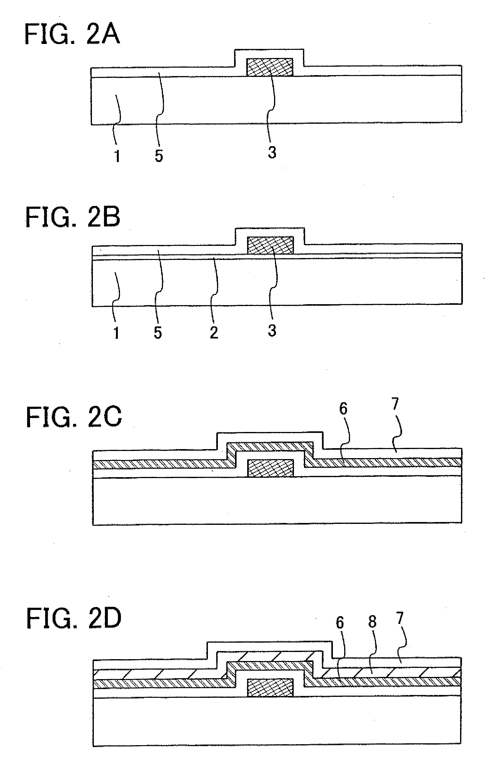
[0083]As shown in FIG. 2A, a gate electrode 3 is formed. The thickness of the gate electrode may be 10 to 200 nm over a substrate 1. The substrate 1 may be formed by using the material shown in Embodiment 1. Here, a glass substrate is used.
[0084]An insulating film 2 containing silicon oxide (SiOx), silicon nitride (SiNx), silicon oxynitride (SiOxNy) (x>y), silic...
PUM
| Property | Measurement | Unit |
|---|---|---|
| frequency | aaaaa | aaaaa |
| band gap | aaaaa | aaaaa |
| thickness | aaaaa | aaaaa |
Abstract
Description
Claims
Application Information
 - R&D
- Intellectual Property
- Life Sciences
- Materials
- Tech Scout
- Unparalleled Data Quality
- Higher Quality Content
- 60% Fewer Hallucinations
Browse by: Latest US Patents, China's latest patents, Technical Efficacy Thesaurus, Application Domain, Technology Topic, Popular Technical Reports.
© 2025 PatSnap. All rights reserved.Legal|Privacy policy|Modern Slavery Act Transparency Statement|Sitemap|About US| Contact US: help@patsnap.com


