
System and method for data routing

a data processing apparatus and data routing technology, applied in the direction of electrical apparatus, digital transmission, data switching network, etc., can solve the problems of large amount of silicon area needed for these data buses, placing a significant design constraint,

Inactive Publication Date: 2004-09-23
AIRSPAN NETWORKS INC PTSGE CORP
View PDF7 Cites 72 Cited by
  • Summary
  • Abstract
  • Description
  • Claims
  • Application Information

AI Technical Summary

Benefits of technology

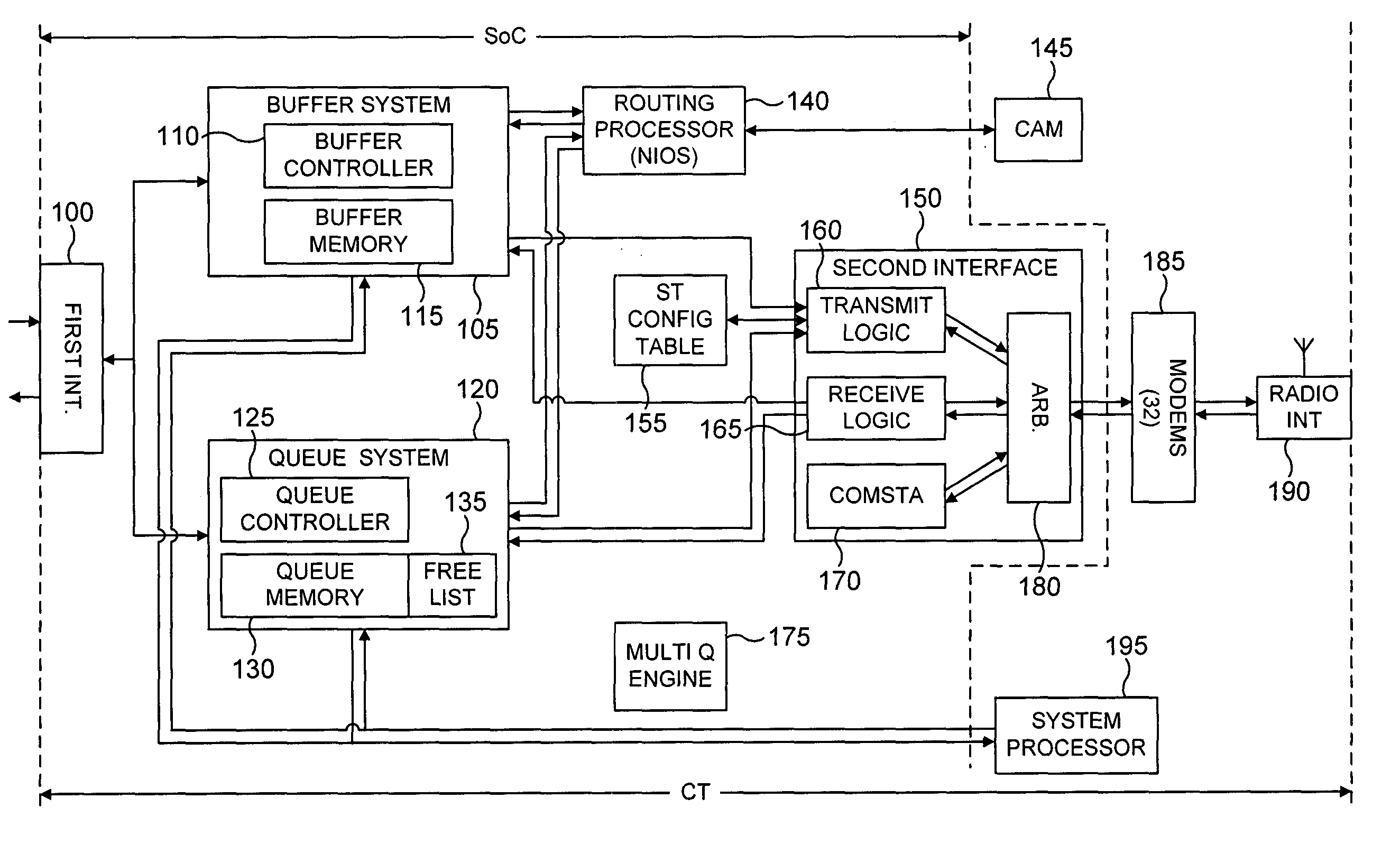
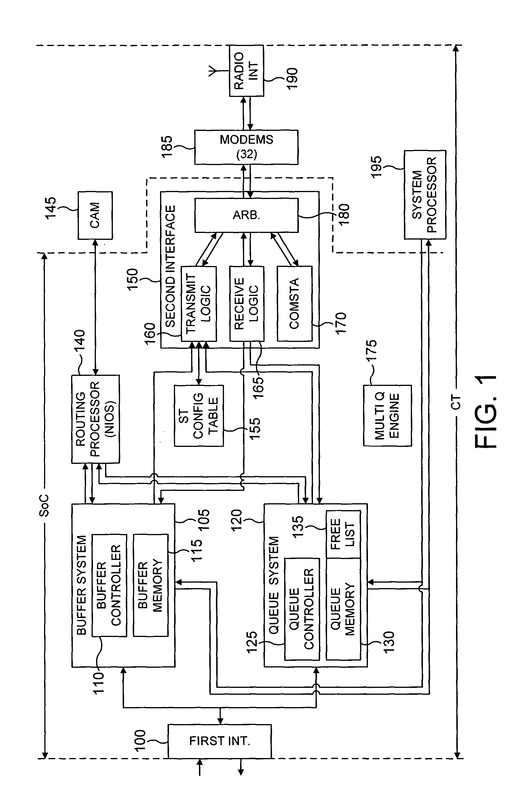
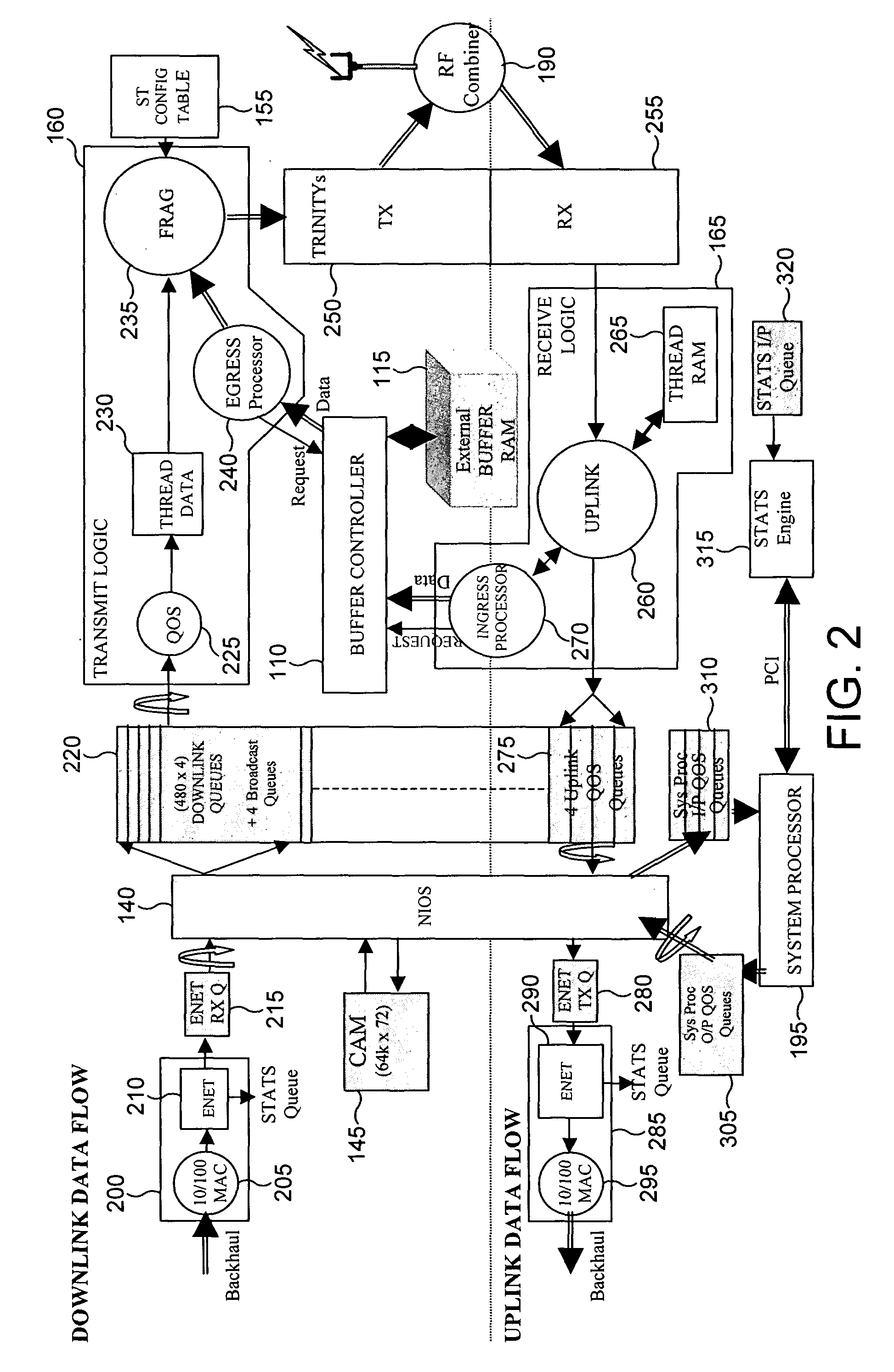
[0009] With this approach, each processing element is responsive to the receipt of a queue pointer from an associated connection queue to perform its predetermined control functions in respect of the associated data packet. Thus, the passing of a data packet between the first and second interfaces is controlled by the routing of the associated queue pointer between a number of the connection queues. Since the queue pointers are significantly smaller in size than the data packets in the buffers to which they refer, then such an approach significantly reduces the bandwidth required for the connections between the various processing elements, thus enabling a significant reduction in the size and cost of the data processing apparatus, particularly in situations where it is desired to implement the data processing apparatus in a SoC.
[0012] It will be appreciated that the queue pointer can take a variety of forms. However, in one embodiment, the queue pointer contains a pointer to the buffer containing the associated data packet, and an indication of the length of the data packet within the buffer. By directly providing an indication of the length of the data packet, this enables more efficient access to the data packet within the buffer when required, since the data packet can be accessed directly without having to determine where the data ends within the buffer.
[0019] In one embodiment, the buffer command further indicates an offset into the buffer to identify a data packet portion to be accessed. This provides an efficient technique for specifying particular portions of data to be accessed within the buffer.
[0041] Situations may occur where an individual data packet needs to be broadcast to multiple destinations. With the earlier mentioned prior art techniques where control information is appended to each payload data, this would necessitate the distribution of multiple copies of the data, along with the relevant control information for each copy, amongst the various processing elements of the data processing apparatus. However, in accordance with preferred embodiments of the present invention, the efficiency of such broadcasting of data packets is significantly improved, since the data packet is stored once in a particular buffer, and a queue pointer is then generated for each destination, each queue pointer containing a pointer to that buffer. Hence, whilst multiple queue pointers are distributed between the various processing elements of the data processing apparatus, the data packet is not, and instead the data packet is stored once within a single buffer.
[0044] It will be appreciated that the data processing apparatus can be embodied in any suitable form. However, in one embodiment, the data processing apparatus is a System-on-Chip (SoC). In this implementation, the benefits of the present invention become significantly marked, since the use of the present invention significantly reduces the amount of silicon area that would otherwise be required, thereby reducing costs and improving yield of the SoC.
[0047] In accordance with this second aspect of the present invention, a server-client architecture is embodied in a SoC. In such an architecture, data will typically need to be able to be input to the server logic unit from each client logic unit, the server logic unit will need to be able to issue data to each of the client logic units, and each client logic unit will need to be able to issue commands to the server logic unit. Using a typical SoC design approach, this would require each of the input buses from the client logic units to the server logic unit to have a width sufficient not only to carry the input data traffic but also to carry the commands to the server logic unit, resulting in a large amount of silicon area being needed for these data buses. However, in accordance with the second aspect of the present invention each client logic unit is operable, when a service is required from the server logic unit, to multiplex the command with any input data on the associated unidirectional input bus, thus avoiding the requirement for the input bus to have a width any larger than that required to handle the larger of the command data or input data.

Problems solved by technology

However, it is desirable to reduce the cost and size of such a data processing apparatus, and accordingly the above approach places a significant constraint on the design.
This is due to the fact that SoC designs typically only allow one driver to be provided for each bus.
If complex systems are sought to be embodied in a SoC design, this can lead to a significant amount of silicon area being dedicated to the buses interconnecting the various logic units.
Using a typical SoC design approach, this would require each of the input buses from the client logic units to the server logic unit to have a width sufficient not only to carry the input data traffic but also to carry the commands to the server logic unit, resulting in a large amount of silicon area being needed for these data buses.

Method used


Image

  • System and method for data routing
  • System and method for data routing
  • System and method for data routing

Examples


Embodiment Construction

[0069] For the purposes of describing a data processing apparatus of an embodiment of the present invention, an implementation in a wireless telecommunications system will be considered. Before describing the preferred embodiment, an example of such a wireless telecommunications system in which the present invention may be employed will first be discussed with reference to FIG. 12.

[0070] FIG. 12 is a schematic overview of an example of a wireless telecommunications system. The telecommunications system includes one or more service areas 12, 14 and 16, each of which is served by a respective central terminal (CT) 10 which establishes a radio link with subscriber terminals (ST) 20 within the area concerned. The area which is covered by a central terminal 10 can vary. For example, in a rural area with a low density of subscribers, a service area 12 could cover an area with a radius of 15-20 Km. A service area 14 in an urban environment where there is a high density of subscriber termin...


PUM


Abstract

The present invention provides a data processing apparatus and method for a telecommunications system, the apparatus being operable to pass data packets between a first interface connectable to a first transport mechanism and a second interface connectable to a second transport mechanism. The data processing apparatus comprises a plurality of processing elements including the first and second interfaces, and operable to perform predetermined control functions to control the passing of data packets between the first and second interfaces, predetermined connections being provided between the processing elements. A plurality of buffers are provided, with each buffer being operable to store a data packet to be passed between the first and second interfaces, and a plurality of connection queues are also provided, each connection queue being associated with one of the predetermined connections, and being operable to store one or more queue pointers, each queue pointer being associated with a data packet by providing an identifier for the buffer containing that data packet. Each processing element is then responsive to receiving a queue pointer from an associated connection queue to perform its predetermined control functions in respect of the associated data packet, whereby the passing of a data packet between the first and second interfaces is controlled by the routing of the associated queue pointer between a number of the connection queues.

Description

[0001] 1. Field of the Invention[0002] The present invention relates to a data processing apparatus and method for data routing, and in particular to a data processing apparatus and method for a telecommunications system operable to pass data packets between a first interface connectable to a first transport mechanism and a second interface connectable to a second transport mechanism.[0003] 2. Description of the Prior Art[0004] It is known to provide a data processing apparatus within a telecommunications system in order to handle the routing of data packets between two different transport mechanisms, for example where a first transport mechanism may be a non-proprietary transport mechanism such as the Ethernet transport mechanism, and the second transport mechanism may be a proprietary transport mechanism, or a different non-proprietary transport mechanism, such as may be used within a wired or wireless network. In particular, the data processing apparatus may be used to perform ph...

Claims


Application Information

Patent Timeline
Patent Type & Authority Applications(United States)
IPC IPC(8): H04L12/56H04L29/06
CPCH04L12/5693H04L45/00H04L45/302H04L47/621H04L47/6215H04L49/205H04L69/22H04L49/30H04L49/351H04L49/90H04L49/901H04L49/9047H04L49/25H04L47/50
Inventor HOLDEN, ROGER JOHN
Owner AIRSPAN NETWORKS INC PTSGE CORP
Learn More