Ceramic cutting insert of polycrystalline tungsten carbide
- Summary
- Abstract
- Description
- Claims
- Application Information
AI Technical Summary
Benefits of technology
Problems solved by technology
Method used
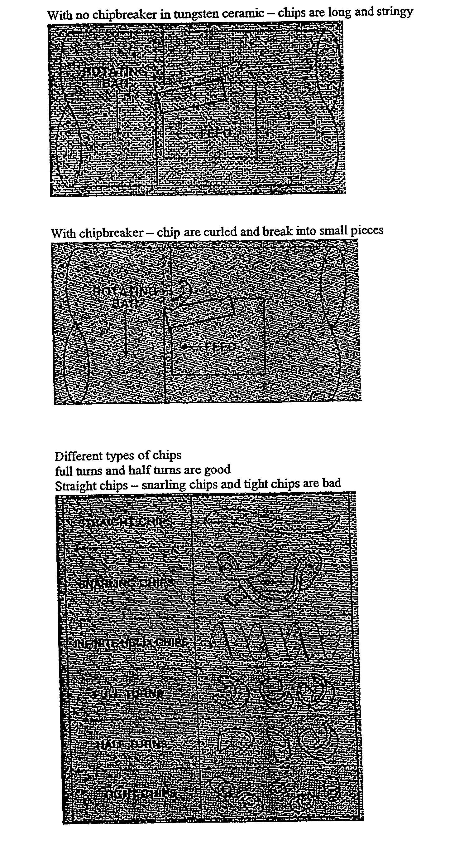
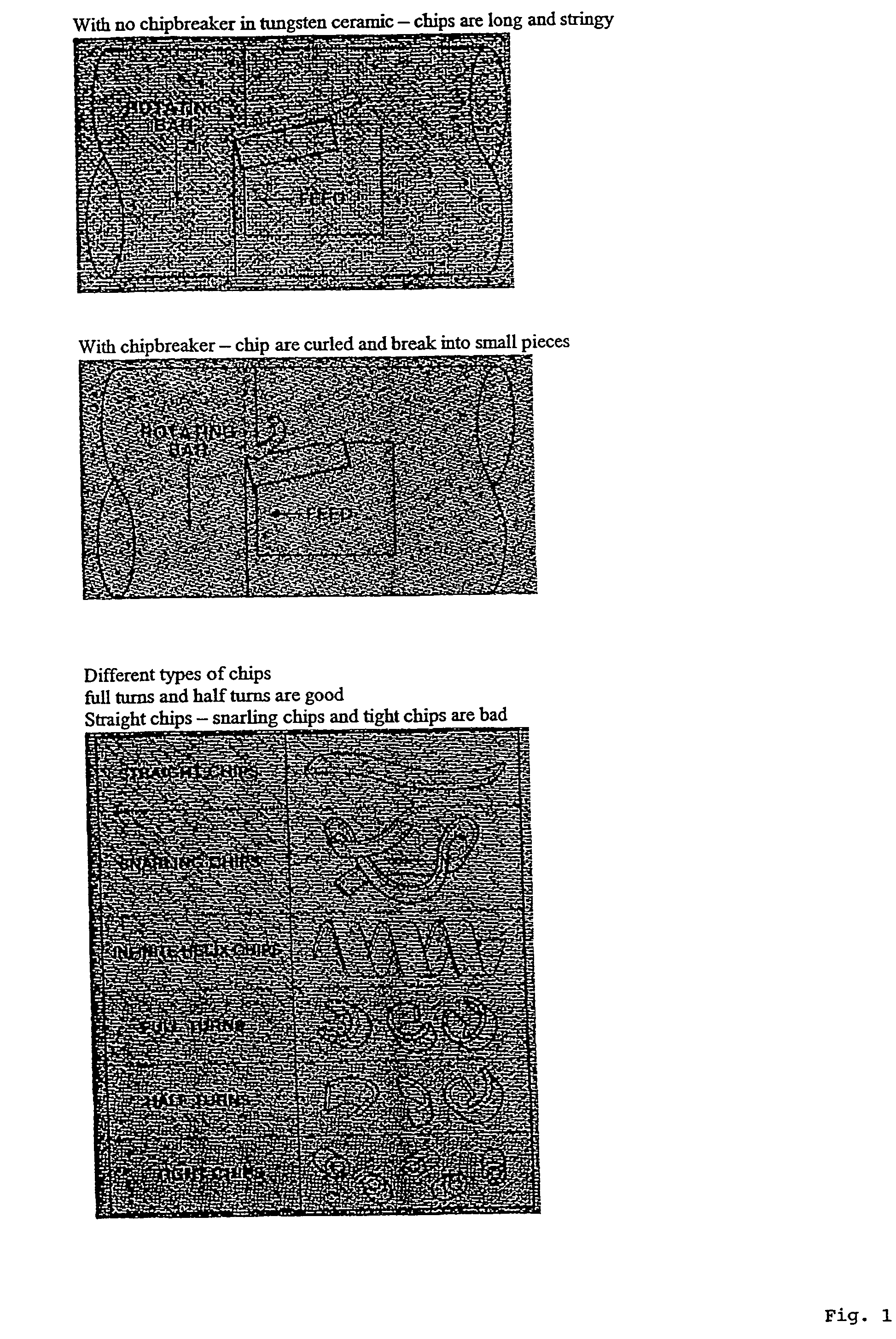
Image

Examples
Embodiment Construction
[0027] Tungsten carbide powder (particle size of 1 micron), 0.35% VC and 2.25% wax was spray dried into a pressable powder. The powder was pressed in a cavity with punches and dies to have to form of the insert shape and chip breaker put into the ceramic body at the same time. The ceramic cutting insert was heated to 400.degree. C. under argon to remove the wax binder. After all traces of wax binder was gone the insert was heated to 1900.degree. C. until parts became dense. While maintaining temperature pressure (50,000 psi) was applied to remove porosity.
[0028] Other Emdodiments
[0029] It is to be understood that while the invention has been described in conjunction with the detailed description thereof, the foregoing description is intended to illustrate and not limit the scope of the invention, which is defined by the scope of the appended claims. Other aspects, advantages, and modifications are within the scope of the following claims.
PUM
| Property | Measurement | Unit |
|---|---|---|
| Grain size | aaaaa | aaaaa |
| Grain size | aaaaa | aaaaa |
| Fraction | aaaaa | aaaaa |
Abstract
Description
Claims
Application Information
 - R&D
- Intellectual Property
- Life Sciences
- Materials
- Tech Scout
- Unparalleled Data Quality
- Higher Quality Content
- 60% Fewer Hallucinations
Browse by: Latest US Patents, China's latest patents, Technical Efficacy Thesaurus, Application Domain, Technology Topic, Popular Technical Reports.
© 2025 PatSnap. All rights reserved.Legal|Privacy policy|Modern Slavery Act Transparency Statement|Sitemap|About US| Contact US: help@patsnap.com