
Apparatus and method for forming battery terminal posts

a technology of battery terminals and apparatuses, which is applied in the direction of auxillary welding devices, cell components,foundry moulding apparatus, etc., can solve the problems of slow and complicated introduction of lead, no practical way to build up lead from the bottom, and inability to heat molds, etc., to achieve good thermal contact, low thermal mass, and high electrical and thermal resistance

Inactive Publication Date: 2003-11-13
TIE GEL MFG
View PDF7 Cites 1 Cited by
  • Summary
  • Abstract
  • Description
  • Claims
  • Application Information

AI Technical Summary

Benefits of technology

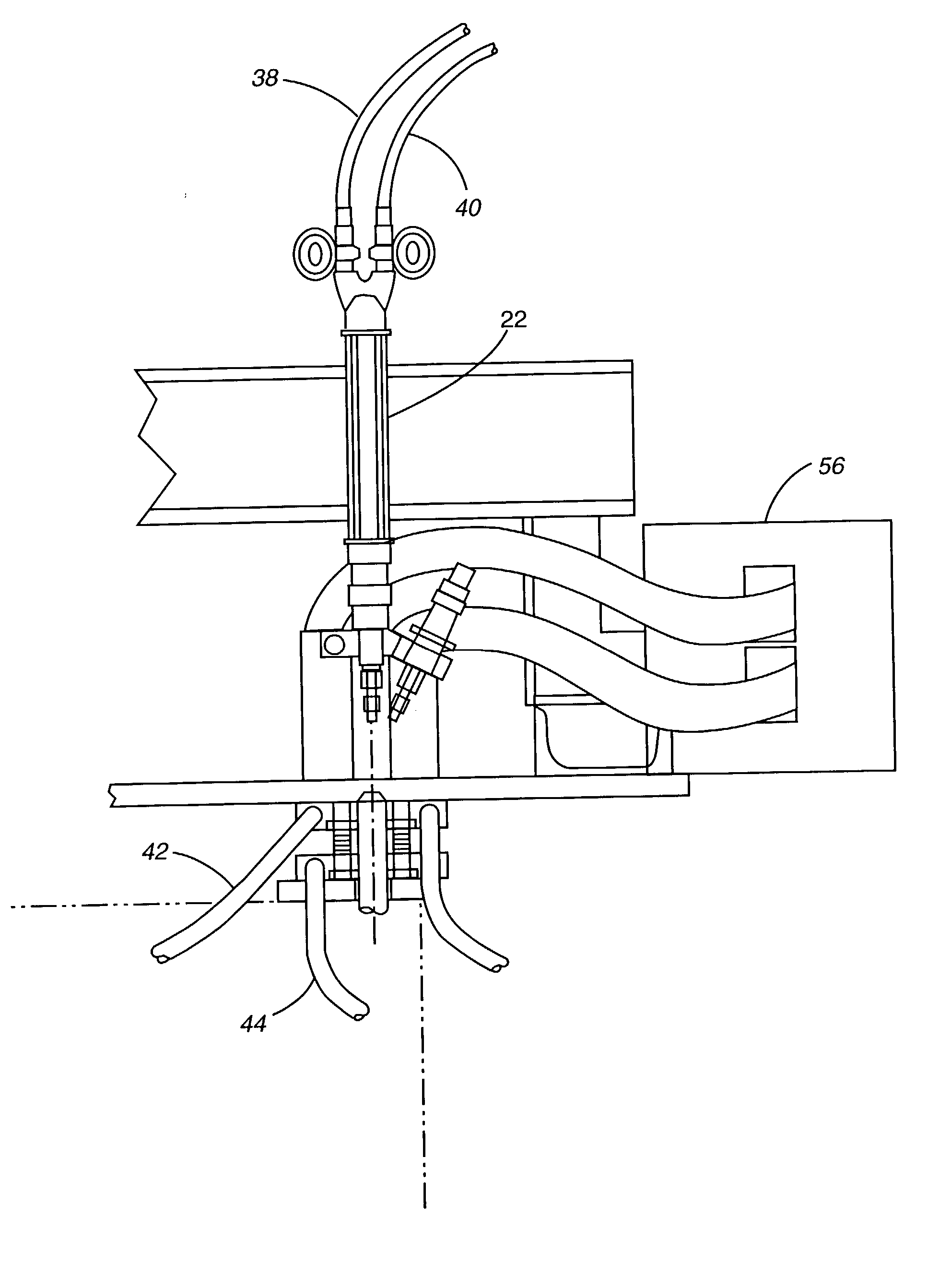
[0014] In accordance with our invention, the majority of the heat is supplied to the lead via the mold. The mold material in contact with the lead has a low thermal mass and high electrical and thermal resistance. It is also desirable to melt some of the lead to provide good thermal contact between the mold and the post. This allows for faster heat transfer and lower mold temperatures.
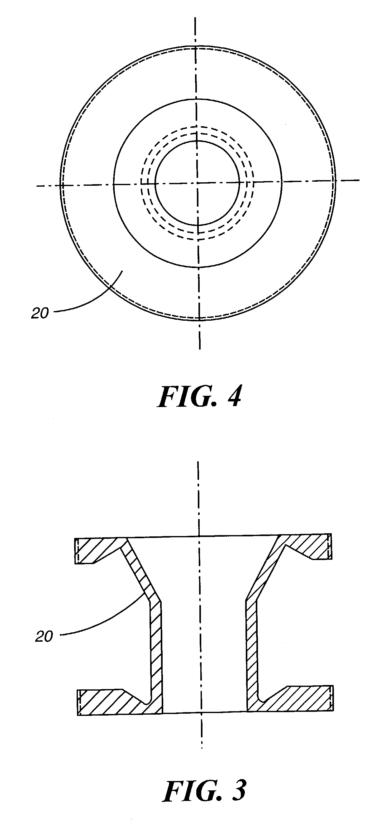
[0027] The mold material in contact with the lead must have a low thermal mass similar to or preferably less than the thermal mass of the lead battery terminal. This translates into a mold of thin walls 0.2 to 0.02 inch. Thin walls minimize the amount of heat that must be applied and removed from the mold. The thin mold walls also allow faster heat transfer.

Problems solved by technology

In the prior art, there is no practical way to build up the lead from the bottom to the top within the mold.
However, as soon as the hot lead begins to run down into the mold, it freezes or solidifies preventing the torch from heating any further down in the mold.
Attempting to heat the mold from the inside by flame, introduction of very hot lead, or a hot poker (i.e. soldering iron) is slow and complicated.
It is also very difficult to place the heat where one prefers to apply it; which is near the base of the mold.
This causes the lead to shrink during cooling.
Various problems have been noted in the prior art.

Method used


Image

  • Apparatus and method for forming battery terminal posts
  • Apparatus and method for forming battery terminal posts
  • Apparatus and method for forming battery terminal posts

Examples


Embodiment Construction

are:

1 Heat Volume of Thermal Conductivity Density Capacity Material Mass BTU / in hr sq. Material lb / cu in BTU / lb F cu in. BTU / F ft. F Titanium 0.164 0.139 0.07 0.0016 119 Inconel 0.3 0.106 0.07 0.0022 103 Nickel 0.322 0.105 0.07 0.0023 639 Iron 0.284 0.108 0.07 0.0021 523 Aluminum 0.097 0.215 0.07 0.00146 1,540 Copper 0.324 0.092 0.07 0.020 2,730 Lead 0.410 0.031 0.30 0.0038* 241 *Thermal mass of post. All other entries are thermal mass of mold in direct contact with the post. Mold volume of material assumes 0.030" mold wall thickness.

[0030] The thermal mass of potential mold materials are similar except for copper, which has an unacceptably high thermal mass.

[0031] Aluminum has a low thermal mass and a very high thermal conductivity, but it could melt if heated to an excessively high temperature.

[0032] The best method of applying heat to the mold is by passing electric current through the mold itself and through the lead. The placement of heat is controlled by varying the wall thick...


PUM

PropertyMeasurementUnit
thicknessaaaaaaaaaa
electric currentaaaaaaaaaa
melting pointaaaaaaaaaa

Abstract

In a battery post burning apparatus, the majority of the heat is supplied to the lead via the mold in which the finished post is being formed. The mold material in contact with the lead has a low thermal mass and high electrical and thermal resistance. The mold material may be Meehanite cast iron. Another material, such as titanium, may be used. If so, it is preferable to coat it with silver solder and provide a copper insert, where the electrical and thermal connection is being made. In another embodiment, a magnetic field is provided to break up any oxide coatings on the mold surfaces.

Description

[0001] This application claims the benefit of our prior U.S. Provisional Patent Application No. 60 / 377,867 filed May 7, 2002 which application is incorporated herein by reference as if fully set forth.[0002] 1. Field of the Invention[0003] This invention relates to the formation of battery terminal posts, and, more particularly, to improvements in the method and apparatus for forming low and high profile battery terminal posts in situ.[0004] 2. Description of the Art[0005] The present invention deals with low and high profile battery terminal posts. Additional lead has to be added to terminal posts that are pre-formed on the battery group strap. The terminal post is positioned up through a bushing on the cover of the battery.[0006] In the prior art, it is known to form battery terminal posts by lowering a mold over a bushing embedded in the battery cover through which a portion of an unfinished terminal post is projecting from the battery terminal group strap positioned inside the b...

Claims


Application Information

Patent Timeline
Patent Type & Authority Applications(United States)
IPC IPC(8): B22D25/04H01M2/30
CPCB22D25/04Y10T29/4911H01M2/307H01M50/561Y02E60/10
Inventor TIEGEL, RALPH G.WEGNER, PAUL
Owner TIE GEL MFG
Learn More