
Method for operating an electronic vapour inhaler

a vapour inhaler and electronic technology, applied in the field of electronic vapour inhalers, can solve the problems of inhalation, charring of aerosol-forming substrates, and inhalation of harmful chemicals such as carbon dioxide and tar, and achieve the effects of low thermal mass, rapid heating, and convenient handling

Active Publication Date: 2021-06-15
JT INT SA
View PDF10 Cites 1 Cited by
  • Summary
  • Abstract
  • Description
  • Claims
  • Application Information

AI Technical Summary

Benefits of technology

[0013]The induction heatable element has a low thermal mass and can, therefore, be heated rapidly in the presence of the alternating electromagnetic field generated by the induction coil of the induction heating arrangement. The induction heatable element may, for example, be heated from ambient temperature to approximately 250° C. in 0.2 seconds. The low thermal mass also allows the induction heatable element to rapidly cool in the absence of the alternating electromagnetic field, as the heat energy is transferred into the surrounding non-liquid flavour-release medium. By intermittently energising the induction coil to provide an intermittent alternating electromagnetic field, and hence intermittent or pulsed heating and cooling of the induction heatable element, a large amount of energy can be delivered to the induction heatable element without burning or overheating the non-liquid flavour-release medium. As a result of heat transfer from the induction heatable element to the non-liquid flavour-release medium, for example by conduction, radiation and convection, the non-liquid flavour-release medium, or at least one or more localised regions thereof, can be rapidly heated to a temperature within an operating temperature range at which a vapour is generated having suitable characteristics (including flavour and aroma) for inhalation by a user. The intermittent or pulsed heating and cooling of the induction heatable element combined with the low thermal mass of the induction heatable element ensures that the non-liquid flavour-release medium does not reach a temperature above the operating temperature range at which overheating, burning or charring occur and enables the non-liquid flavour-release medium to be heated rapidly to a temperature in the operating temperature range.
[0014]The method may comprise varying the pulse frequency of the power supplied to the induction coil to intermittently energise the induction coil. The method may comprise varying the pulse amplitude of the power supplied to the induction coil to intermittently energise the induction coil. The method may comprise varying the duty cycle of the power supplied to the induction coil to intermittently energise the induction coil. Controlling the pulse frequency and / or the pulse amplitude and / or the duty cycle provides control over the pulsed heating and cooling of the induction heatable element and therefore allows the operating temperature of the non-liquid flavour-release medium to be controlled.
[0015]The pulsed heating and cooling of the induction heatable element may heat the non-liquid flavour-release medium to an operating temperature in an operating temperature range having a lower limit of between 150° C. and 200° C. and an upper limit of between 200° C. and 250° C. Typically, the operating temperature range is between 180° C. and 240° C. In the case where the non-liquid flavour-release medium is a tobacco material which might typically have a combustion temperature in the region of 380° C., it will be apparent that the upper limit of the operating temperature range is substantially lower than the combustion temperature. As a consequence, charring and burning of the tobacco material is avoided and this ensures that the vapour generated by heating the tobacco material has optimum characteristics.
[0017]The method may comprise a second operating phase in which the induction coil is intermittently energised to generate an intermittent alternating electromagnetic field which provides pulsed heating and cooling of the induction heatable element to maintain the average temperature of the non-liquid flavour-release medium within the operating temperature range. The strength of the alternating electromagnetic field is typically lower during the second operating phase than during the first operating phase. This is possible because the component parts of the electronic vapour inhaler have already been heated up during the first operating phase and because the amount of moisture and vapour-forming medium in the non-liquid flavour-release medium has decreased. Thus, less energy is needed to maintain the average temperature of the non-liquid flavour-release medium within the operating temperature range.

Problems solved by technology

Although inhalation of the vapour creates a physical sensation which is similar to conventional smoking, harmful chemicals such as carbon dioxide and tar are not produced or inhaled because there is no combustion.
This is due to the higher thermal mass of the resistance heating element which has a slow response.
This may cause charring of the aerosol-forming substrate and would be highly undesirable as it produces an aerosol with an unpleasant or ‘off’ taste.
This may also begin to generate the undesirable compounds that are generated in conventional, lit-end cigarettes, as a result of combustion.
Furthermore, even at the very high temperatures described in WO 2014 / 102091, the start-up period is still unacceptably long especially when compared to the instantaneous availability of a lit-end cigarette or an e-cigarette which heats and atomises a liquid.

Method used


Image

  • Method for operating an electronic vapour inhaler
  • Method for operating an electronic vapour inhaler

Examples


Embodiment Construction

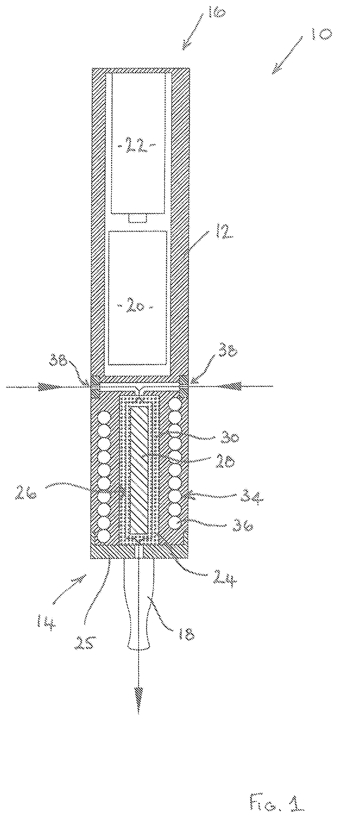
[0025]Embodiments of the present disclosure will now be described by way of example only and with reference to the accompanying drawings.

[0026]Referring initially to FIG. 1, an electronic vapour inhaler 10 comprises a generally elongate housing 12 having a proximal end 14 and a distal end 16. The electronic vapour inhaler 10 includes a mouthpiece 18 at the proximal end 14 through which a user can inhale vapour generated by heating a non-liquid flavour-release medium 30. The electronic vapour inhaler 10 includes a control arrangement 20, e.g. in the form of a microprocessor, and a power source 22 in the form of one or more batteries which could, for example, be inductively rechargeable.

[0027]The housing 12 includes a chamber 24 containing the non-liquid flavour-release medium 30. The chamber 24 is located at the proximal end 14 of the housing 12 adjacent to the mouthpiece 18, but this is not strictly necessary and it could be located at any suitable position between the proximal end ...


PUM


Abstract

A method is provided for operating an electronic vapour inhaler (10) comprising an induction heating arrangement (34), the induction heating arrangement (34) comprising an induction coil (36) for generating an alternating electromagnetic field to heat an induction heatable element (28) and thereby heat a non-liquid flavour-release medium (30). The method comprises intermittently energising the induction coil (36) to generate an intermittent alternating electromagnetic field which provides pulsed heating and cooling of the induction heatable element (28).

Description

CROSS-REFERENCE TO RELATED APPLICATIONS[0001]The present application is a national phase entry under 35 U.S.C. § 371 of International Application No. PCT / GB2016 / 053168, filed Oct. 13, 2016, published in English, which claims priority to Great Britain Application No. 1518244.7 filed Oct. 15, 2015, the disclosures of which are incorporated herein by reference.TECHNICAL FIELD[0002]The present disclosure relates generally to electronic vapour inhalers and more particularly to a method for operating an electronic vapour inhaler in which a non-liquid flavour-release medium is heated to produce a vapour for inhalation by a user.TECHNICAL BACKGROUND[0003]The use of electronic vapour inhalers (also known as electronic cigarettes, e-cigarettes and personal vaporisers), which can be used as an alternative to conventional smoking articles such as lit-end cigarettes, cigars, and pipes, is becoming increasingly popular and widespread. The most commonly used electronic vapour inhalers are usually ...

Claims


Application Information

Patent Timeline
Patent Type & Authority Patents(United States)
IPC IPC(8): A24F47/00G05B15/02H05B6/06A24F40/20A24F40/465A24F40/50
CPCA24F47/008G05B15/02H05B6/06A24F40/465A24F40/50A24F40/20A61M15/06A24F47/00A24F40/46A24F40/57
Inventor GILL, MARKVANKO, DANIELBRVENIK, LUBOS
Owner JT INT SA
Learn More