
Method and composition for coating mat and articles produced therewith

a technology of coating mats and compositions, which is applied in the field of methods and compositions for coating mats and articles produced therewith, can solve the problems of affecting the cohesion strength of glass mats is typically too low to resist the pulling-away force of high-wind shear vacuums, and the application of gypsum boards is more difficult, so as to achieve a higher degree of uniform coating penetration

Inactive Publication Date: 2003-07-17
ATLAS ROOFING
View PDF36 Cites 42 Cited by
  • Summary
  • Abstract
  • Description
  • Claims
  • Application Information

AI Technical Summary

Benefits of technology

[0024] New coating methods which yield the coated glass mat expose a sufficient amount of coating to the glass mat to provide a uniform depth penetration and thereby achieve the increased tensile strength. The method facilitates a high degree of coating depth penetration (e.g., up to 75%) and yet no significant change in coating percentage composition by weight per square unit area. Because of the new coating techniques, the prior art glass mat substrate has a disproportionate increase in tensile strength relative to the increase in final product weight. The coated glass mat webs are much stronger and more weatherproof than prior art similar webs.
[0025] One of the new coating techniques involves increasing a wrap angle of the glass mat substrate around an applicator roll thereby increasing exposure of the coating to the glass mat substrate. Other techniques also provide a substantial increase in tensile strength.
[0037] The improved coating techniques thus facilitate increased exposure of the coating mixture to a glass mat substrate, and thereby a uniformly deeper penetration of the coating into the interior spaces of the glass mat. The penetration is to a depth of at least 25%, but preferably less than about 75%, of the thickness of the mat, i.e., not so far that it penetrates entirely. Such increased exposure and uniformly deep penetration is accomplished by various techniques including but not limited to those hereinafter specifically described.
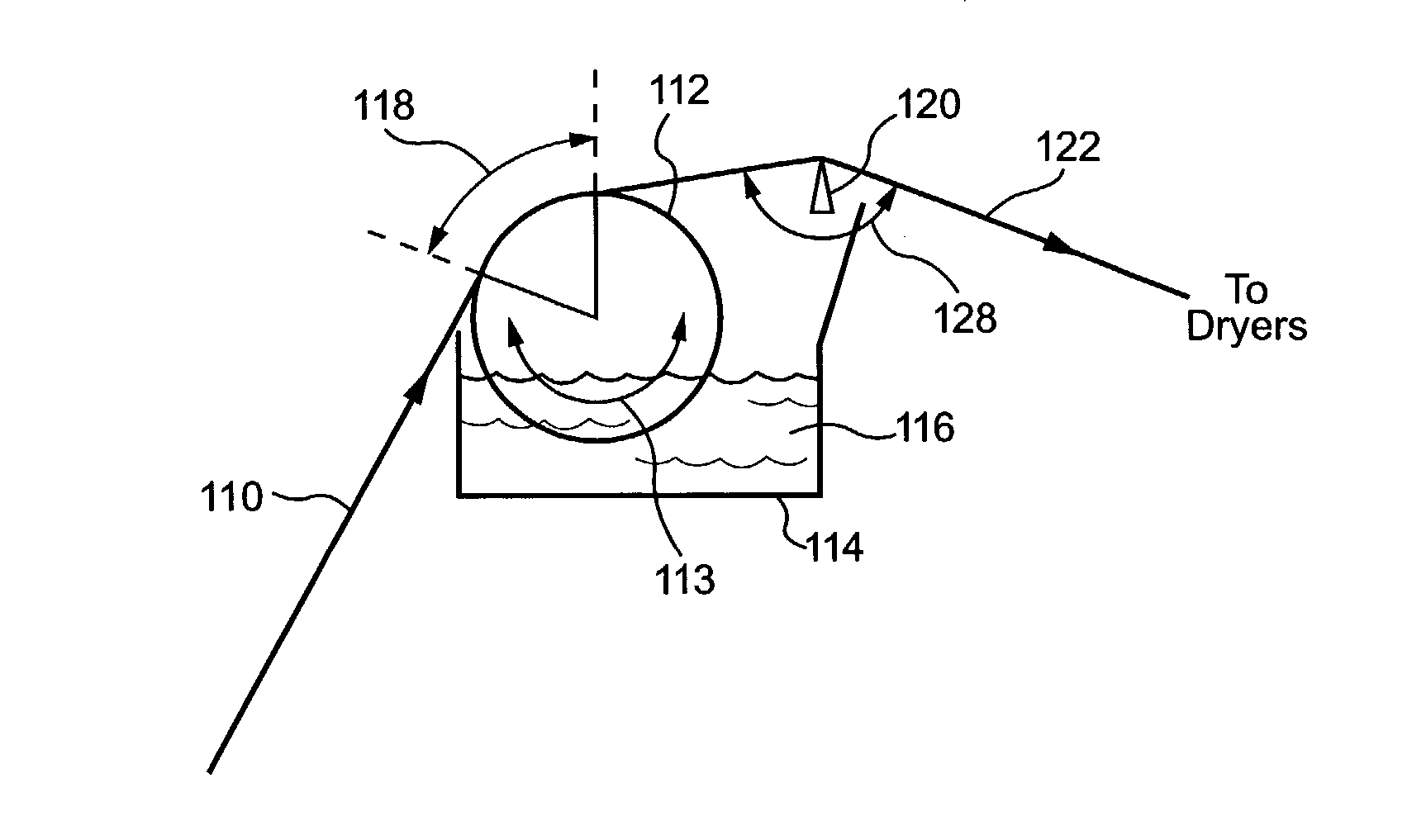
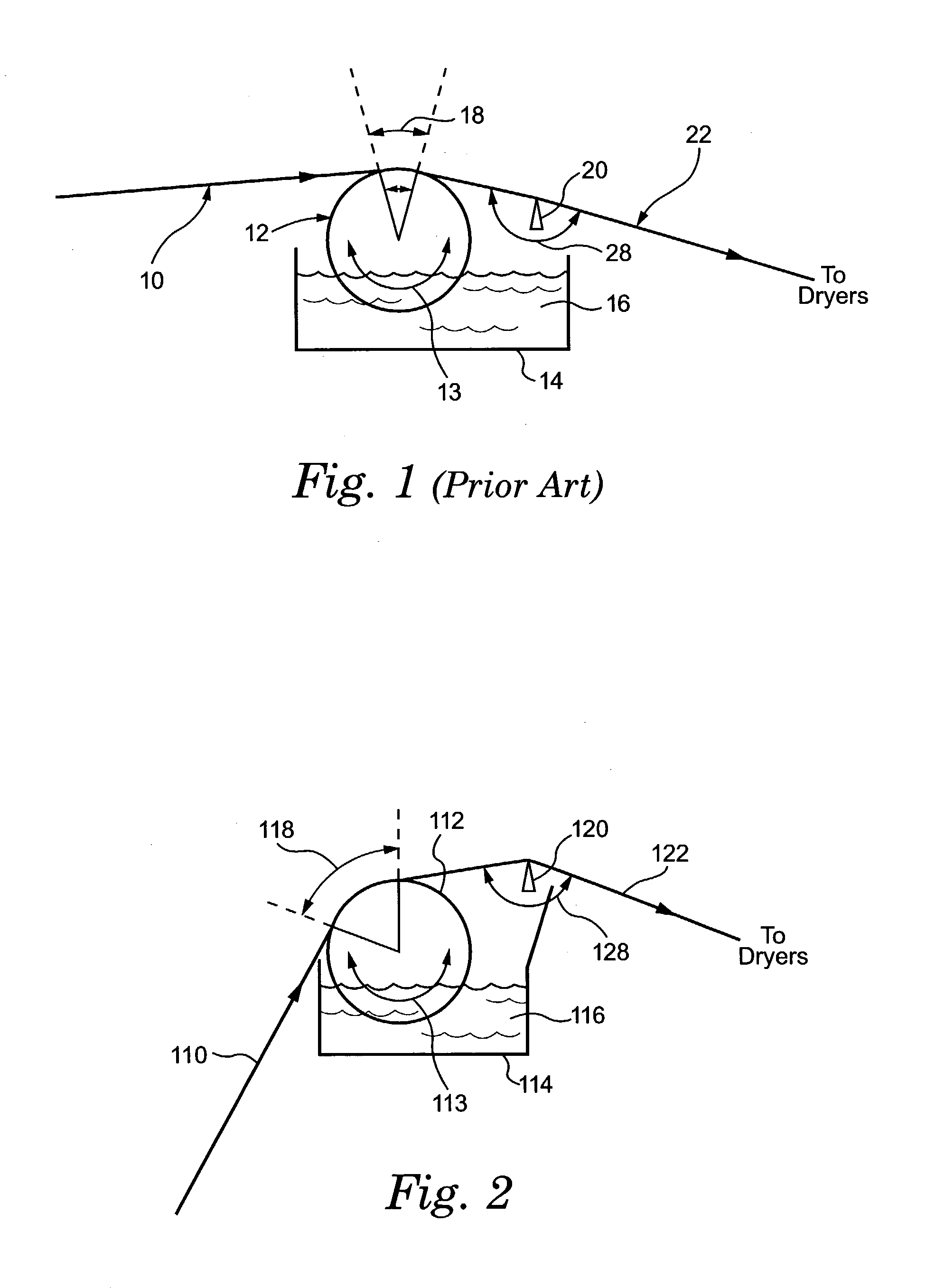
[0040] In contrast to the prior art process of FIG. 1, the process implemented by the FIG. 2 apparatus utilizes a higher degree of wrap-arc 118 around the applicator roll 112 and a smaller (less than 180-degrees) wrap angle 128 around scraper blade 120. This tighter wrapping method provides an increased exposure of coating mixture 116 to the glass mat substrate 110, and thereby a higher degree of uniform coating penetration into the glass mat. The degree of penetration is between approximately 25% up to 75% of the thickness into the glass mat substrate. In this coating method, the wrap-arc 118 is much larger (above about 20-degrees) than wrap-arc 18 of FIG. 1. Specifically, wrap-arc 118 is in a range from about 20 degrees to 80 degrees depending upon other operational parameters (such as, for example, speed of applicator roll 112). Likewise, wrap angle 128 of the new method is noticeably sharper than wrap angle 28 of the prior art (about 170 degrees).
[0041] It should be understood that it is the degree of exposure of the coating material 116 to the glass mat substrate 110 that is increased by the new processing techniques and which results in the more uniform penetration of the coating into the glass mat substrate. The degree of exposure or availability of the coating 116 is a different phenomena than the actual amount of acquisition by glass mat substrate 110 of the coating mixture. Indeed, using the new exposure enhancing technique, no more coating is actually applied for penetration into the glass mat substrate. Rather, there is more opportunity for uniform acquisition of the coating 116 by the glass mat substrate 110.
[0045] It was mentioned previously that the wrap-arc 118 is in a range of from about 20 degrees to 80 degrees. In one example, the wrap-arc 118 extends about 80 degrees and the applicator roll is rotated at a nominal angular velocity which is just slightly faster than the linear velocity of the glass mass substrate. Yet in another example, the wrap-arc 118 extends a lesser amount (e.g. 40 degrees), but the applicator roll is driven at an increased angular velocity which affords essentially the same exposure as the first example. Thus, the new techniques can be combined in order to achieve the desired exposure of the coating 116 to the glass mat substrate 110, thereby enhancing uniform coating penetration. The uniform coating penetration facilitates the improved tensile strength of the coated glass mat, e.g., a tensile strength in the machine direction which is at least 1.33 times greater than that of the glass mat substrate prior to coating.

Problems solved by technology

A vulnerability for a laminated board made with a coated glass mat facer can be the structural integrity of the glass mat which comprises the facer.
Experience has generally shown that the cohesive strength of any glass mat is typically too low to resist the pulling-away force of high wind shear vacuums, whether the glass mat be incorporated either in a stucco wall or under a fully adhered single-ply membrane roofing system.
Uncovered glass fibers are exposed and thus more subject to deleterious forces.
The complications of using coated glass mats as ingredients in building materials such as a board are compounded when the glass mats interface with certain other materials which comprise the board core.
Most gypsum board applications are more difficult, and much stronger coated glass mats are required.
While the problems presented by gypsum could perhaps be solved by using heavier raw glass mat substrates, such an option is quite expensive.
A challenge, therefore, is strengthening the coated glass mat (e.g., strengthening the facer) without substantially increasing costs.
In almost all cases, the subject of facer stability was an issue.
Mildew and mold have been a problem with the original multi-ply paper facers used on gypsum board.
Unfortunately, the paper facers also might not allow water vapor to escape.
As alluded to above, some coated glass mat prior art facer products are ineffective or unusable as a facer for a gypsum board.
However, the ordinary prior art coated glass mat facers do not have adequate tensile strength.
In addition to lacking tensile strength, ordinary coated glass mat facers can face difficulty in becoming adequately bonded to the gypsum slurry.
As previously mentioned, the failure occurs because some fibers are left uncovered and the bonding strength of the so-called "binder" material between individual glass fibers is not strong enough to prevent failure.
Just after a non-woven glass mat is formed on a drainage wire, a complex binder chemical is added, but this is barely strong enough to hold individual fibers together.
If the coated glass mat facer has too much glass mat exposed such that the gypsum cannot cover it essentially entirely, the resultant board is unacceptable.
On the other hand, if not enough glass fibers (which serve to anchor the gypsum) are left exposed, the resultant board is not acceptable.
In both cases, the finished board can fail a flexural stress test, or worse, break at the job-site.

Method used


Image

  • Method and composition for coating mat and articles produced therewith
  • Method and composition for coating mat and articles produced therewith
  • Method and composition for coating mat and articles produced therewith

Examples


example 2 (

PRIOR ART)

[0056] As Example 2, a coated glass mat facer fabricated by Elk Corporation in accordance with the prior art process of U.S. Pat. No. 5,965,257 and known as "ISO FACER 1" was evaluated. The coated glass mat facer of Example 2 weighed about 99-lbs / MSF, and measured (with a caliper) a thickness of about 0.034-inches. Thirty samples of tensile test data for the mat of Example 2 are shown in Table 2, the first column of Table 2 showing tensile test data with respect to the machine direction (M.D.) and the second column showing tensile test data with respect to the cross-machine direction (C.M.D.).

[0057] Comparison of the tensile strengths for Example 1 and Example 2 as set forth in Table 1 and Table 2, respectively, show that even with more thickness and higher weight, the product of Example 2 is considerably weaker than the product made as Example 1. Yet both Example 1 and Example 2 pale in contrast to the substantially higher tensile strengths achieved by the remaining Examp...

example 3

[0059] Example 3 utilized the same coating batch mixture as Example 1. The coating of Example 3 was applied to a glass mat using the process of FIG. 2. The glass mat weighed 14.5-pounds per MSF (thousand square feet).

[0060] Table 3 shows samples of tensile strength data for Example 3. As with the Table 4 mats discussed subsequently, for the Table 3 mats the sample size tested was 3-inches wide by 10-inches long, with 1-inch at each end inside the jaws, and the tensile test jaws were pulled at the speed of 1-inch per minute. The coated glass mats of Example 3 had an average thickness of 0.026-inches and weighed an average of 85-lbs per 1,000-square feet (MSF). Of that finished weight, about 70.5-lbs / MSF was coating and 14.5-lbs / MSF was glass mat.

4TABLE 3 Sample # Machine Direction Cross Mach. Dir. 1 101.6-lbs / 3-inch 114.1-lbs / 3-inch 2 113.5-lbs / 3-inch 111.8-lbs / 3-inch 3 140.2-lbs / 3-inch 113.1-lbs / 3-inch 4 116.9-lbs / 3-inch 102.9-lbs / 3-inch 5 120.5-lbs / 3-inch 95.5-lbs / 3-inch 6 110.9-lb...

example 4

[0063] The coating batch for Example 4 was the same as for Example 1, but was applied using the process of FIG. 2 to a glass mat (Dura-Glass 7503) sold as weighing 14.5-pounds per MSF (thousand square feet), but actually weighing 14.9-pounds per MSF. The coated glass mat weighed 89.1-pounds per MSF on average. As with the Example 1 mats, the Example 4 mat sample size tested was 3-inches wide by 10-inches long, with 1-inch at each end inside the jaws, and the tensile test jaws were pulled at the speed of 1-inch per minute. Approximately the same coating weight was applied (an average of 74.2-pounds / MSF), but the improved processing techniques made the coating penetrate more uniformly and further into the glass mat substrate. In doing this, the approximate same coating weight created a final product with substantially higher tensile strength, as indicated by Table 4.

5 TABLE 4 Example 4 Tensile Data Sample # M.D. C.M.D. 1 122 110 2 114 108 3 141 113 4 117 103 5 121 96 6 123 120 7 112 1...


PUM

PropertyMeasurementUnit
wrap angleaaaaaaaaaa

Abstract

A coated glass mat comprises a glass mat substrate having non-woven glass fibers and a coating which essentially uniformly penetrates the glass mat substrate to desired fractional thickness of the coated glass mat. The coating imparts a tensile strength to the coated glass mat which on average is at least 1.33 times greater than the tensile strength of the glass mat substrate without the coating. In example embodiments, penetration of the coating into the glass mat substrate preferably extends to a depth of from twenty five percent of a thickness of the coated glass mat to seventy five percent of the thickness of the coated glass mat. Moreover, a non-coated thickness of the coated glass mat is sufficiently thick for bonding purposes with, e.g., a gypsum slurry or other core materials such as thermoplastic or thermosetting plastics. The coating has a porosity in a range of from 1.3 CFM to 5.0 CFM, e.g., the coating comprises a coating blend which provides the coated glass mat with a porosity sufficient to allow water vapor to escape from a gypsum slurry when heated. The coating is preferably a coating blend comprised of water, latex binder, inorganic pigment, and inorganic binder.

Description

[0001] This application claims the priority and benefit of U.S. Provisional Application Serial No. 60 / 341,277, entitled "METHOD AND COMPOSITION FOR COATING MAT AND ARTICLES PRODUCED THEREWITH", which is incorporated herein by reference.[0002] 1. Field of the Invention[0003] The field of the invention pertains to mats, webs, or facers for the building construction industry, such as gypsum board fiberglass facers and thermosetting polyiso foam insulation board facers, as well as processes for making / applying such facers and products utilizing such facers.[0004] 2. Related Art and Other Considerations[0005] Many forms of weather resistant webbed sheets have been developed for the building construction industry for installation as an "underlayment" under shingles or under siding. Examples of such webbed sheets, also called "construction paper", range from the old original "tar paper", up to the spun-bonded polyolefin house wraps of the present day.[0006] Various types of webbed sheets h...

Claims


Application Information

Patent Timeline
Patent Type & Authority Applications(United States)
IPC IPC(8): B05C1/12B05C11/04B28B19/00B28B23/00B32B17/10B32B27/36D06N3/00D06N7/00
CPCB05C1/12B05C11/04B28B19/0092B28B23/0006B32B17/10018Y10T428/273D06N3/0022D06N3/0063D06N2205/023Y10T428/237B32B27/36Y10T442/2926Y10T442/2139Y10T442/20Y10T428/249955Y10T442/60Y10T442/2992Y10T428/249956
Inventor BUSH, PHILIPBLANPIED, ROBERT H.MURPHY, FREDDIE LEEDUBOSE, JIMMY ROGERS
Owner ATLAS ROOFING
Learn More