
Mold goods and insert molding method

a technology of insert molding and goods, which is applied in the direction of manufacturing tools, pedestrian/occupant safety arrangements, and catheter, etc., can solve the problems of high cost, high labor intensity, and inability to meet the needs of customers, and achieve high degree of uniformity and high uniformity

Inactive Publication Date: 2007-06-28
NIHON PLAST CO LTD
View PDF4 Cites 22 Cited by
  • Summary
  • Abstract
  • Description
  • Claims
  • Application Information

AI Technical Summary

Benefits of technology

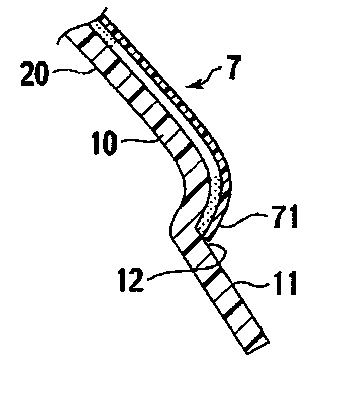
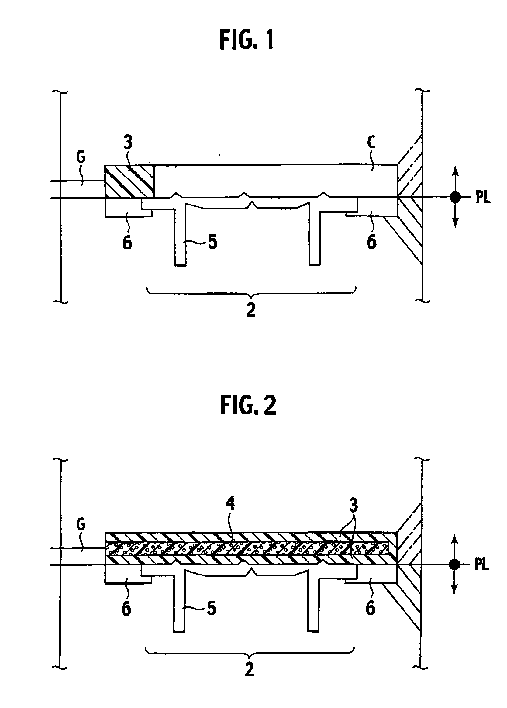
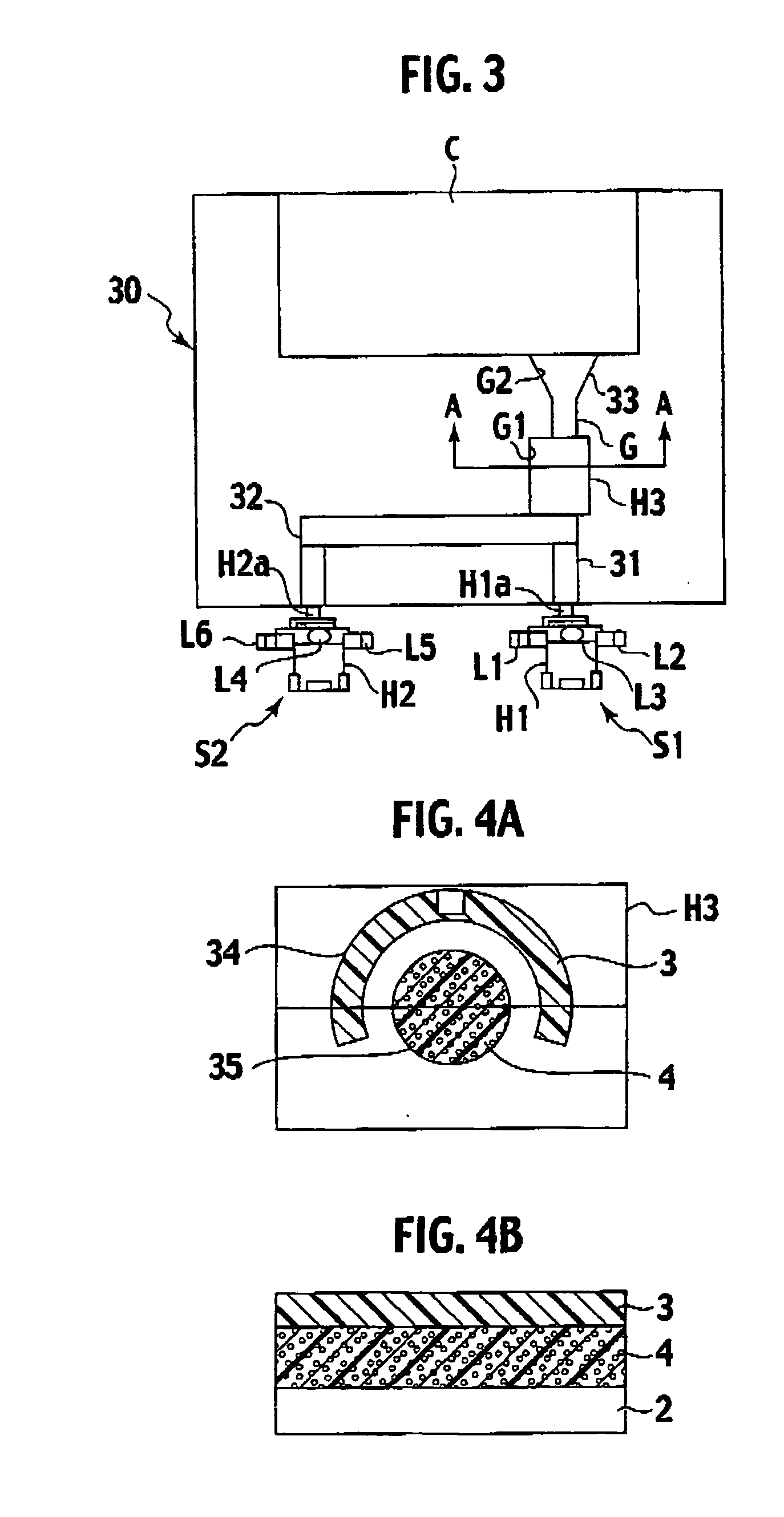
[0010] It is an object of the present invention to provide a manufacturing method, as a method that can mold an integral skin foam in which a foamed layer and a skin layer are laminated, under a normal pressure (atmospheric pressure), in a single process, allowing a laminate article to be obtained in which a mold goods manufactured by this molding method has a high degree of uniformity over an appreciable wide range of the article. Further, it is an object of the invention to provide a laminate mold goods in which the foamed layer and skin layer have a high uniformity along a base member, over a prescribed length in a flow direction of a skin forming material.

Problems solved by technology

For the protection of a cushion layer to have a secured durability against surface wear or such of products, the skin layer is unavoidable to interior parts of automobile that are required to stand the use in by far severe circumstances.
In this document, disclosed technique needs two steps of molding process for molding a laminate of foamed layer and skin layer, and is troublesome, inefficient in productivity, and impractical.
This however needs a dedicated facility for pressure reduction of the cavity, and a mold to be high of air-tightness, besides a required time for pressure reduction to a prescribed pressure, and is very troublesome and costs high, so that one would have to say the employment is difficult.
This method might be yet insufficient, as an increased uniformity is required between foamed layer and skin layer.
In particular, for such a large-scale mold goods as an upper facia of instrument panel, it is difficult to give an even tactile impression in a vicinity of an injection point (gate) and at a location distant therefrom, such that due to the non-foamed layer being thick at locations vicinal to the injection point and extremely thinned in thickness at location distant from the injection, the vicinity of the injection point has a firm touch while the location distant therefrom gives a very soft feel.
The flow of polyurethane resin forming a skin layer may not arrive at locations further distant from the injection point, thus failing to have a skin layer spread over an entire product surface, with a resultant exposure of foamed layer in some cases, constituting a difficulty in applications to panel-like large-scale components or such.

Method used


Image

  • Mold goods and insert molding method
  • Mold goods and insert molding method
  • Mold goods and insert molding method

Examples


embodiment examples

Example 1

[0084] Description is now made of an example of molding of an airbag cover panel.

[0085] As materials for skin formation, a material for skin layer formation and a material for cushion layer formation were prepared. For the material for skin layer formation, there were prepared polyol having respectively mixed a cross-linker as a 1:1 mixture of an amine system cross-linker and glycol system cross-linker and a catalyst as a combination of a metallic catalyst and an amine system catalyst, having an average molecular weight within a range of 4000 to 6000 or near, and aromatic isocyanate of a crude type containing 90% or more in proportion of trimer and higher multimers, and adjusted for a tack-free time (necessary time for curing) to be within a range of 20 to 30 seconds when mixing. The supply system (first RIM machine) of this material for skin layer generally had a tank for isocyanate, a tank for polyol, a tank for pigment (coloring agent), an injection head, feed lines fo...

example 2

[0092] There will be described a molding of a steering wheel according to another embodiment example. Description is made of a distinctive feature over the foregoing example 1, omitting like points to the above-noted example.

[0093] As materials for skin formation, a material for skin layer formation and a material for cushion layer formation were prepared. For the material for skin layer formation, there were employed, relative to the above-noted example, like polyol, and aliphatic isocyanate, as a non-yellow coloration type adjusted for a tack-free time (necessary time for curing) to be within a range of 20 to 30 seconds when mixing.

[0094] For the material for cushion layer, there were employed polyol having added ethylene glycol as a cross-linker and TEDA as a catalyst, having an average molecular weight within a range of 5000 to 7000 or near, and aromatic polyisocyanate (as a modified type of pure MDI) having, as foaming agent, formic acid added, and carbon dioxide dissolved, a...


PUM

PropertyMeasurementUnit
distanceaaaaaaaaaa
distanceaaaaaaaaaa
thicknessaaaaaaaaaa

Abstract

For a skin, a non-formed polyurethane resin layer at the surface side and a foamed polyurethane resin layer between the non-foamed polyurethane resin layer and a base member are configured to form an integral and uniform layer over and extent from an injection point to a distant point on a surface of the base member, so that an integral skin foam in which such skin layer and foamed layer are laminated can be molded, under an atmospheric pressure, in a single process, allowing for manufacture of a laminate article with a high degree of uniformity over an appreciable wide range of the article, as well as for provision of a laminate mold goods having the skin and foamed layers formed with a high uniformity along the base member, over the length in a flow direction of skin forming material.

Description

BACKGROUND OF THE INVENTION [0001] The present invention relates to a mold goods having a laminated flexible resin skin formed in a desirable location of the mold goods with an appreciable size, and an insert molding method suitable for manufacture of the mold goods. [0002] As a conventional mold goods in which a skin lined with a foamed layer is attached on a base member such as a resin panel, a typical one is manufactured by a method in which a skin layer to be located at an outermost side of the product is premolded by a slash molding as well as a spray skin method or a vacuum molding method, and after this is inserted together with the base member, a polyurethane resin is injected and foamed as for a cushion layer between the skin layer and the base member. [0003] As another well-known method, there is one that has begun to be employed, in which a sheet composed of a vinyl chloride or thermoplastic elastomer sheet (such as of an olefin system or urethane system, sometimes referr...

Claims


Application Information

Patent Timeline
Patent Type & Authority Applications(United States)
IPC IPC(8): B32B3/00B29C39/10B29K75/00B29K105/04B29L9/00B29L31/58B32B5/18B32B27/40B60R21/20B60R21/205B60R21/215B62D1/06
CPCB29C44/0461Y10T428/24612B29C44/12B29C45/1671B29C67/246B29C70/78B29K2075/00B29K2105/04B29L2031/3005B29L2031/3008B29L2031/3035B29L2031/3041B29L2031/3047B32B5/22B32B27/065B32B27/40B29C44/08Y10T428/249981Y10T428/249989B29C44/0446B29C44/06B29C44/1228B29C44/1233B29C44/1266B29C45/14811B29C45/164B29C45/1642B29C70/681
Inventor YAMADA, SHUJI
Owner NIHON PLAST CO LTD
Learn More