
Tip of soldering iron, process for producing the same, and electrical soldering iron and electrical solder sucking iron including the iron tip

一种制造方法、烙铁头的技术,应用在烙铁、制造工具、焊接位等方向,能够解决无法得到满意、自由度小等问题,达到提高耐侵蚀性或焊锡浸润性、焊锡浸润性高的效果

Inactive Publication Date: 2006-01-04
HAKKO CO LTD
View PDF1 Cites 6 Cited by
  • Summary
  • Abstract
  • Description
  • Claims
  • Application Information

AI Technical Summary

Problems solved by technology

In this regard, even if the optimal material is selected according to the type of solder used, satisfactory results cannot be obtained due to the small degree of freedom of choice.

Method used


Image

  • Tip of soldering iron, process for producing the same, and electrical soldering iron and electrical solder sucking iron including the iron tip
  • Tip of soldering iron, process for producing the same, and electrical soldering iron and electrical solder sucking iron including the iron tip
  • Tip of soldering iron, process for producing the same, and electrical soldering iron and electrical solder sucking iron including the iron tip

Examples


Embodiment Construction

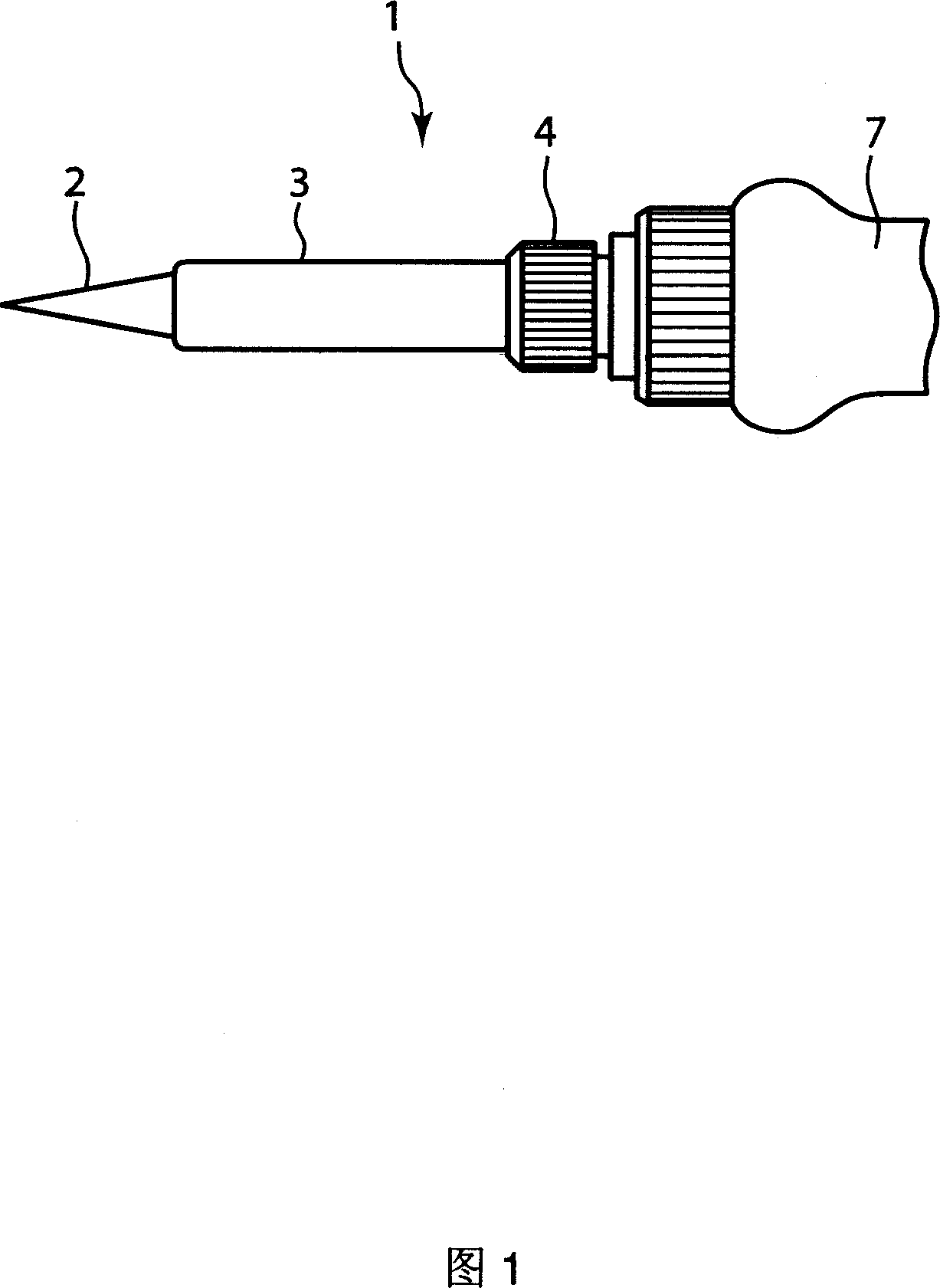
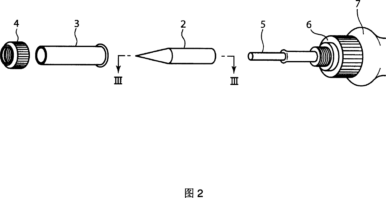
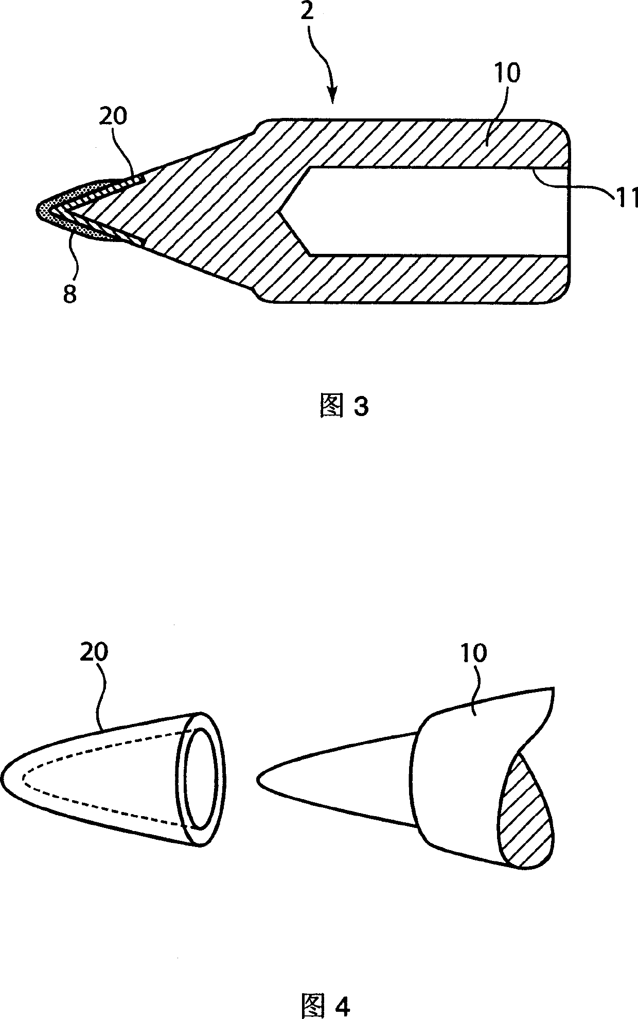
[0076] A first embodiment of the present invention will be described with reference to Figs. 1 to 16 . FIG. 1 is a front view of the vicinity of the tip of the soldering iron 1, and FIG. 2 is an exploded perspective view thereof. The tip part of the electric soldering iron 1 is provided with a soldering iron tip member 2 (corresponding to a soldering iron tip for soldering) which is housed in the protective tube 3 and whose conical tip protrudes from the protective tube 3 . The protective tube 3 is fixed on the threaded joint 6 of the electric soldering iron 1 by the cap nut 4 . In the soldering iron tip unit 2 , a concave portion 11 is provided inside the cylindrical main body covered by the protective tube 3 (see FIG. 3 ). The ceramic heater 5 protruding from the main body 7 of the electric soldering iron 1 is assembled in the concave portion 11 so as to be fitted therein. The ceramic heater 5 is a heating element that generates heat by turning on a power switch not shown ...


PUM

PropertyMeasurementUnit
purityaaaaaaaaaa
particle diameteraaaaaaaaaa

Abstract

A tip 2 for handling solder used as a soldering bit of an electric soldering iron or an electric solder sucking iron, in which a soldering iron tip end member 20 formed of a metal particle sintered body manufactured using a powder metallurgy process is provided at the forward end of a soldering bit core 10 made of copper or a copper alloy. Used for the metal particle sintered body are: a sintering base material in which particles of iron, nickel, and cobalt are combined as needed; and when a need arises, a first sintering additive in which particles of copper, silver, tin, boron, and carbon are combined as need, or a second sintering additive in which particles of vanadium, niobium, tantalum, chromium, and molybdenum are combined as needed.

Description

technical field [0001] The present invention relates to a soldering iron tip for soldering, in particular to a soldering iron tip part for an electric soldering iron or a suction nozzle of an electric heating tin-absorbing iron. A soldering iron tip for soldering with erosion measures, and a manufacturing method thereof, also relate to an electric soldering iron or an electric heating tin-absorbing soldering iron using the soldering iron tip. Background technique [0002] Connections and joints in the electronics industry are usually carried out by welding. The welding method is mainly divided into group welding method (batch welding) and manual welding method (manual welding). [0003] Mass soldering methods include: a flow soldering method in which components or parts are immersed in molten solder after mounting them on a printed circuit board; A reflow soldering method in which components or parts are mounted on the bonding part of the pri...

Claims


Application Information

Patent Timeline
Patent Type & Authority Applications(China)
IPC IPC(8): B23K3/02B22F7/06B22F7/08B23K3/03B23K35/30C22C38/00C22C38/08C22C38/10C22C38/16
CPCC22C38/007B23K3/025B22F2998/00B23K2203/12B22F2009/041B23K3/0338B23K35/3006C22C38/008C22C38/105B22F7/064C22C38/10C22C38/08C22C38/16B22F7/08B23K2103/12B22F3/04B22F3/15B22F9/04
Inventor 长濑隆上谷孝司寺冈巧知
Owner HAKKO CO LTD
Learn More