
Solid electrolytic capacitor, producing method and apparatus thereof

A technology of solid electrolysis and capacitors, applied in the direction of solid electrolytic capacitors, electrolytic capacitor manufacturing, electrolytic capacitors, etc., can solve problems such as the size of solid electrolytic capacitors 1 becoming larger, and achieve elimination of size increase, elimination of possibility, and reduction of internal resistance. Effect

Inactive Publication Date: 2004-09-22
SANYO ELECTRIC CO LTD
View PDF1 Cites 2 Cited by
  • Summary
  • Abstract
  • Description
  • Claims
  • Application Information

AI Technical Summary

Problems solved by technology

However, lead frames made of gold or copper are weaker than lead frames made of 42-alloy, so lead frames made of gold or copper need to be larger than lead frames made of 42-alloy. thickness so as to have sufficient strength to support the capacitor
This makes the size of the solid electrolytic capacitor 1 large

Method used


Image

  • Solid electrolytic capacitor, producing method and apparatus thereof
  • Solid electrolytic capacitor, producing method and apparatus thereof
  • Solid electrolytic capacitor, producing method and apparatus thereof

Examples


Embodiment Construction

[0035] Embodiments of the present invention are described as follows:

[0036] 1. Example of manufacturing method

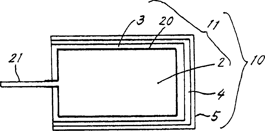
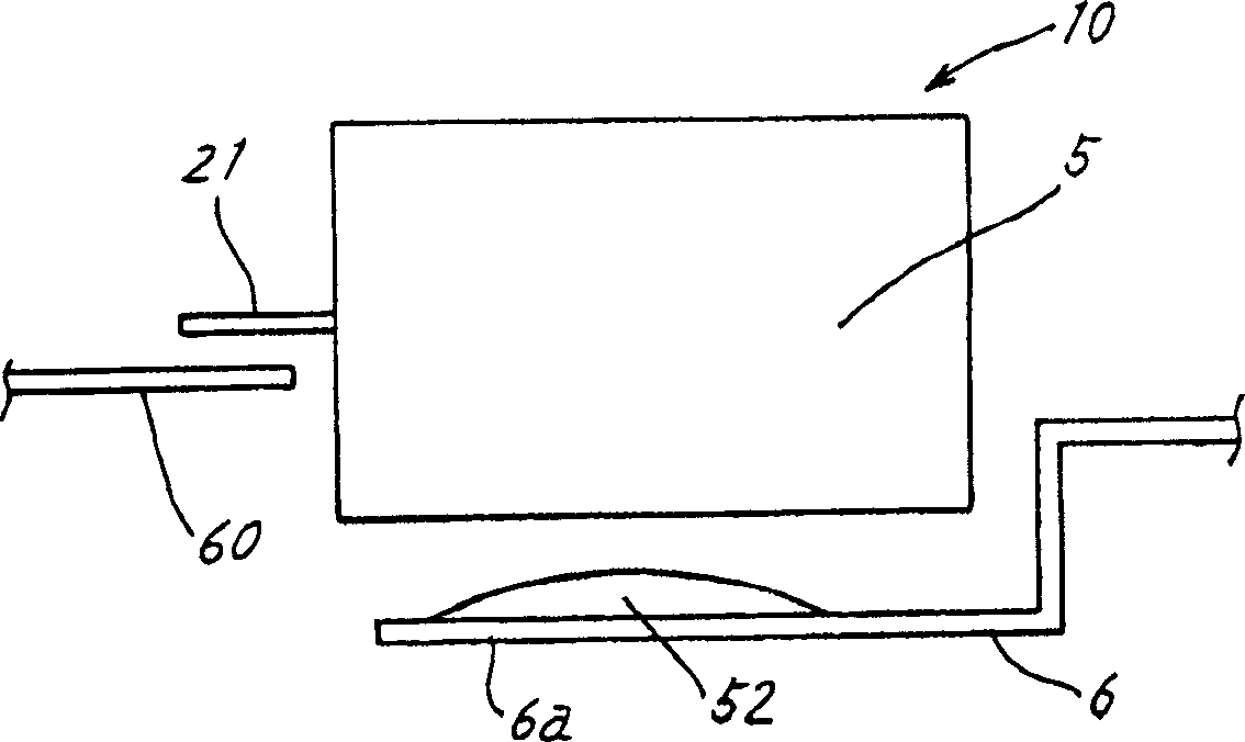
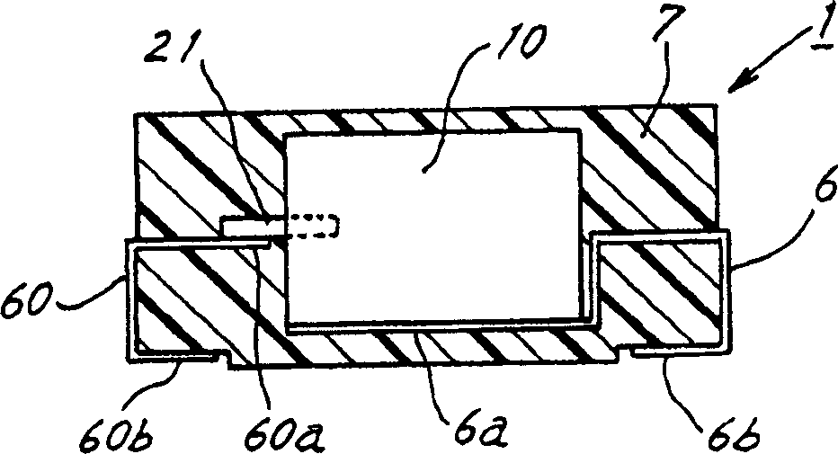
[0037] Referring to Fig. 1, the manufacturing method of the chip type solid electrolytic capacitor according to the present invention comprises: connecting the anode lead wire 21 to the anode body 2 made of valve metal such as Ta, Al or Nb, on the surface of the anode body 2 Electrolytic oxidation treatment is used to form a dielectric oxide film 20, and MnO is used on the oxide film 20 2 Solid conductive substances such as conductive organic compounds form the cathode layer 3 to make the capacitor core 11 . Afterwards, a carbon layer 4 is applied to the cathode layer 3 of the capacitor core, and a silver paste layer 5 is applied to the carbon layer 4 to form a capacitor body 10 . As shown in FIG. 2 , subsequently, the lead frame 6 is connected to the silver paste layer 5 with silver adhesive 52 , and the lead frame 60 is soldered to the anode lead wire 21 . ...


PUM

PropertyMeasurementUnit
thicknessaaaaaaaaaa
electrical conductivityaaaaaaaaaa

Abstract

This invention relates to solid electrolyte capacitors and is intended to decrease the contact resistance between the body of the capacitor and lead frames and the internal resistance of these components. The invention provides a process for producing a solid electrolyte capacitor by forming a dielectric oxide film on an anode body of valve metal, forming a cathode layer of solid conductive substance on the oxide film to prepare a capacitor element, coating the cathode layer of the capacitor element with a carbon layer, coating the carbon layer with a silver paste layer to prepare a capacitor body, and bonding a lead frame to the silver paste layer of the. capacitor body with a silver adhesive. While the capacitor element coated with the carbon layer and a silver paste are being vibrated relative to each other, the capacitor element is dipped in the silver paste and withdrawn therefrom in the direction of the vibration, whereby the carbon layer is coated with the silver paste layer. The surface of the lead frame is partly or entirely formed with a high conductive layer of a material having a higher electric conductivity than the substrate of the lead frame, the high conductive layer extending from a connection to the capacitor body to a connection for an external circuit.

Description

[0001] The present invention is a divisional application of the patent application entitled "Solid Electrolytic Capacitor and Its Manufacturing Method and Manufacturing Equipment" submitted by the applicant to the China Intellectual Property Office on October 14, 1998 with the application number 98124315.0. technical field [0002] The present invention relates to a chip-type solid electrolytic capacitor including a cathode layer of a solid conductive substance, a manufacturing method and a manufacturing device thereof. More particularly, it relates to a member structure for electrically connecting a capacitor core to an external circuit, which structure can ensure a reduction in resistance without increasing the size, and a manufacturing method and manufacturing equipment for the capacitor. Background technique [0003] The solid electrolytic capacitor includes an anode body made of a valve metal such as Al (aluminum) or Ta (tantalum), and a dielectric oxide film formed on t...

Claims


Application Information

Patent Timeline
Patent Type & Authority Applications(China)
IPC IPC(8): H01G9/00H01G9/012
CPCH01G9/0029H01G9/012
Inventor 竹谷丰吉田觉昭上川秀德岸本泰广小岛洋一高松武史药井博
Owner SANYO ELECTRIC CO LTD
Learn More