
Exposure energy predicting method

A technology of exposure energy and energy compensation, which is applied in the field of photolithography technology, can solve the problem of being unable to predict the exposure energy of new products, and achieve the effect of reducing variation and accurate exposure energy

Inactive Publication Date: 2003-03-19
UNITED MICROELECTRONICS CORP
View PDF0 Cites 9 Cited by
  • Summary
  • Abstract
  • Description
  • Claims
  • Application Information

AI Technical Summary

Problems solved by technology

[0007] Another object of the present invention is to provide a method for predicting exposure energy to improve the defect that traditional methods cannot predict its exposure energy for new products

Method used


Image

  • Exposure energy predicting method
  • Exposure energy predicting method
  • Exposure energy predicting method

Examples


Embodiment Construction

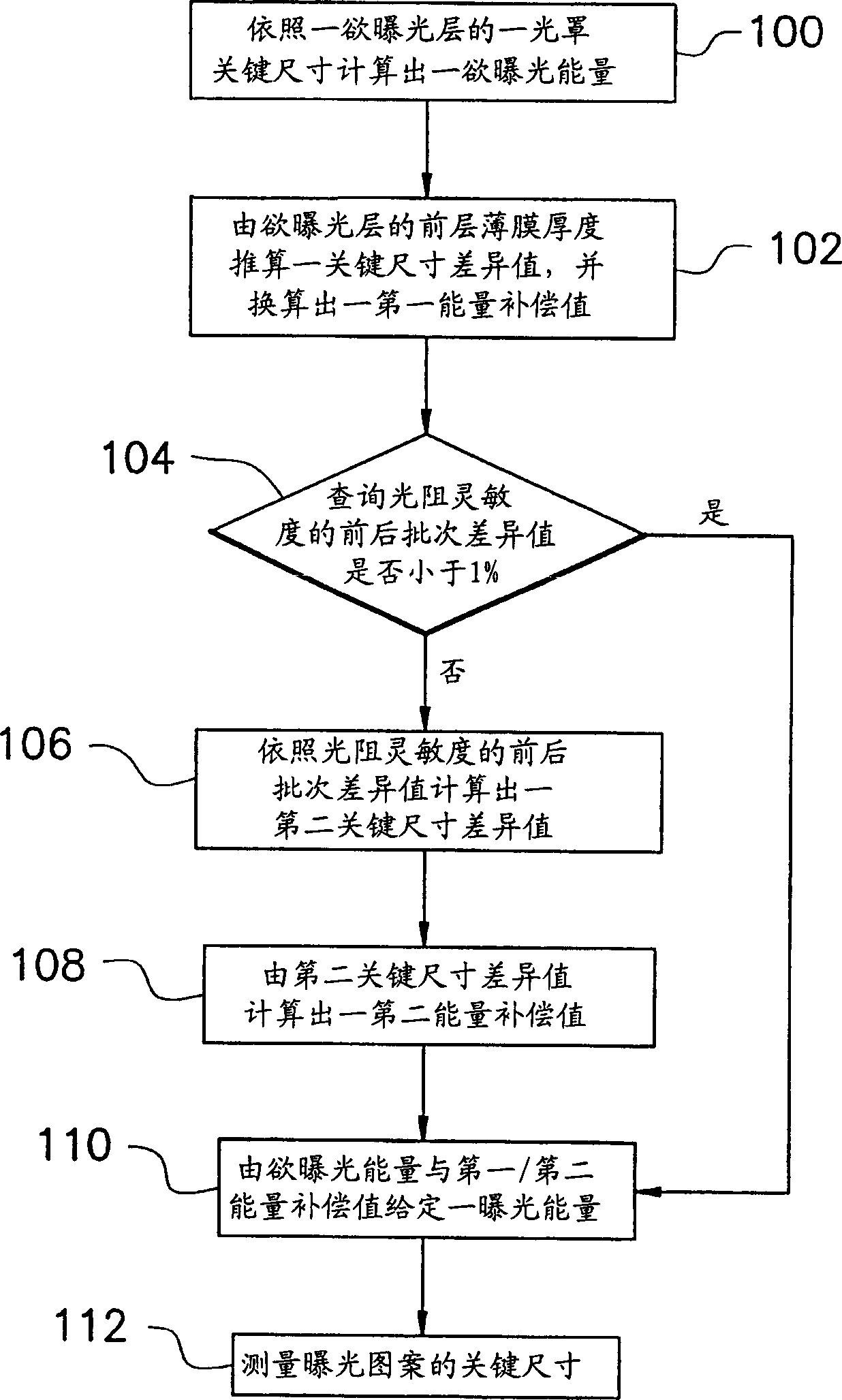
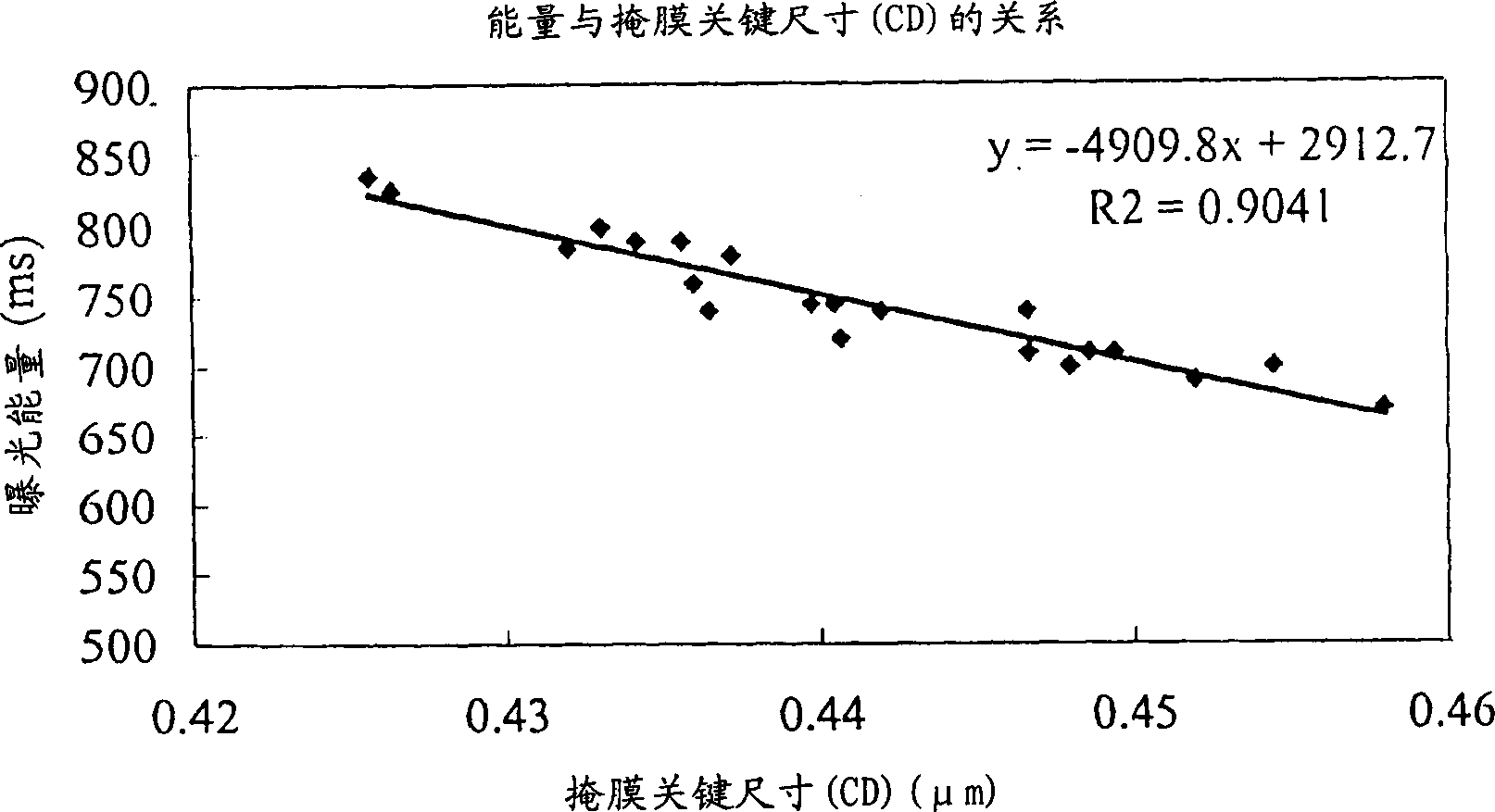
[0018] figure 1 Shown is a flowchart of a method for predicting exposure energy according to a preferred embodiment of the present invention; figure 2 Shown is the linear regression relationship between the critical size of the mask and the exposure energy.

[0019] Please refer to figure 1 The method for predicting exposure energy in this embodiment is to firstly calculate a desired exposure energy according to a critical dimension of a mask of a layer to be exposed (step 100 ). For the method of calculating the energy to be exposed, please refer to figure 2 , figure 2 It is to make a linear regression graph of the historical data of the key size of the mask and the exposure energy, wherein the abscissa is the size of the key size of the mask head, and the ordinate is the value of the exposure energy. Therefore, substitute the mask critical dimension of the layer to be exposed into figure 2 The linear regression equation in can obtain an exposure energy value, which ...


PUM


Abstract

The exposure energy predicting method includes calcualting the exposure energy based on the key size of the exposed layer; obtaining the difference value of the first key size based on the thickness of the front layer film, calculating the first energy compensation value, and checking whether the photoresist sensitivity difference between the adjacent batch is less than 1%. If so, the exposure energy of the layer to be exposed is the sum of the exposed energy and the first energy compensation value. If not, the second key size difference is obtained based on the difference between the adjacent batch, the second energy compensation value is calculated, and the exposure energy of the layer to be exposed is the sum of exposed energy, the first energy compensation value and the second energy compensation value.

Description

technical field [0001] The present invention relates to a photolithography process, and in particular to a method for predicting exposure energy. Background technique [0002] As the integration level of integrated circuits increases, the size of the components of the entire integrated circuit must also be reduced accordingly. The most important thing in the semiconductor process is the photolithography process, which is related to the structure of Metal-Oxide-Semiconductor (MOS) components, such as: the pattern of each layer of thin film (Pattern), and the doping of impurities The area of ​​(Dopants) is determined by the step of photolithography. [0003] The traditional control of the critical dimension (CD) of the photolithography process is to compensate the exposure energy according to the result of the final measured critical dimension after the exposure process, so that the next batch of wafers The circle's key dimension value can be closer t...

Claims


Application Information

Patent Timeline
Patent Type & Authority Applications(China)
IPC IPC(8): G03F7/20
CPCG03F7/70625G03F7/70558
Inventor 张昆源贺万祥黄郁斌蔡立达吴仲雍
Owner UNITED MICROELECTRONICS CORP
Learn More