Coaxial micro pulse laser radar system with micro optical wave surface shaper

A technology of wave surface shaper and laser radar, which is applied in the direction of radio wave measurement system, electromagnetic wave reradiation, instruments, etc., can solve the problems of increasing the volume and weight of the measurement system, low energy efficiency, and detector damage, etc., to improve the complexity and accuracy, improve energy coupling efficiency, reduce volume and weight

Inactive Publication Date: 2005-04-20
CITY UNIVERSITY OF HONG KONG
View PDF0 Cites 0 Cited by
  • Summary
  • Abstract
  • Description
  • Claims
  • Application Information

AI Technical Summary

Problems solved by technology

[0006] 1. Independent emission optical components are required, which increases the volume and weight of the entire measurement system and affects the mobility and mobility measurement performance of the system:
[0007] 2. What is more serious is that this non-coaxial design inevitably brings about a mismatch in the field of view of the receiving and emitting optical components, and its spatial coupling area changes with the field of view and the spatial detection distance, which greatly increases the data The complexity of processing and the difficulty of restoring real atmospheric parameters
[0010] 1. Low energy efficiency: the Gaussian beam emitted by the laser has a large center intensity and a small edge intensity. When the laser beam enters the second mirror of the telescope, its central part cannot effectively exit the telescope due to aperture occlusion, so the energy lost is about 30%-40 %about;
[0011] 2. For the damage to the detector, the laser blocked by the second reflector returns along the original path. After the paraxial light enters the detector, a strong background signal will be generated, and the long-term irradiation of the high-sensitivity avalanche photocell will cause detection The permanent fatigue and damage of the device, and because the background signal is much stronger than the backscatter signal from the atmospheric target, this also increases the difficulty of background compression and signal processing

Method used


Image

  • Coaxial micro pulse laser radar system with micro optical wave surface shaper
  • Coaxial micro pulse laser radar system with micro optical wave surface shaper
  • Coaxial micro pulse laser radar system with micro optical wave surface shaper

Examples


Embodiment Construction

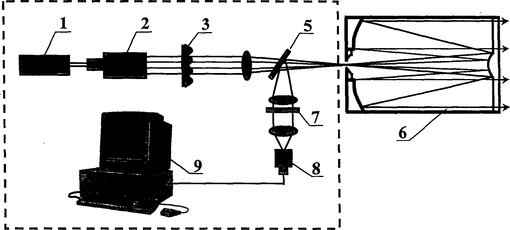
[0038] The structure of the coaxial micro-pulse lidar system proposed by the present invention using the micro-optic wavefront shaper is as follows: figure 1 As shown, it contains a pulsed solid-state laser 1 excited by a laser diode, which generates a frequency-doubled laser beam that is expanded and collimated by a beam expander 2, and the parallel beam generated is incident on the front focal plane of the Fourier transform lens On the micro-optical wavefront shaper 3, the laser beam with Gaussian light intensity distribution is transformed into a flat-top hollow annular beam by the wavefront shaper, and then enters the Fourier transform lens, and after focusing, it is directly sent to the telescope 6 through the polarization beam splitter 5, The beam is further expanded by the telescope into an eye-safe micropulse and then fired at the atmospheric target. After the backscattered light returned by the atmospheric target is received by the same telescope 6, the signal beam i...


PUM

PropertyMeasurementUnit
frequencyaaaaaaaaaa
frequencyaaaaaaaaaa

Abstract

A coaxial micro-pulse laser radar system with a micro-optical wavefront shaper, which is used for atmospheric and cloud measurement, includes a solid-state laser, and the output frequency-doubled laser beam is expanded and collimated, and the micro-optical wavefront shaper converts The Gaussian light intensity distribution is transformed into a flat-top hollow ring beam, which is efficiently coupled with the telescope to become a low-intensity beam-expanding micropulse and shoots to the atmospheric target. The backscattered signal returned from the atmospheric target is collected by the same telescope and filtered by narrow-band interference After the background stray light is filtered out by the chip, the detection signal is sent to the computer processor through the photodiode for analog-to-digital conversion and data processing to obtain the distribution of atmospheric parameters.

Description

technical field [0001] The invention relates to a pulse laser radar system, in particular to a coaxial micro-pulse laser radar system with a micro-optical wavefront shaper for atmospheric detection, which is mainly used for detecting atmospheric parameters such as cloud layer height and aerosol density. Background technique [0002] The lidar system used for measuring atmospheric aerosol density and cloud height generally consists of a pulsed laser light source, laser emitting and receiving unit, signal detection unit, data acquisition and processing unit, the laser beam is fired at the atmospheric target through the emitting optical unit, and the receiving The unit collects backscattered light from atmospheric targets such as clouds and aerosols, and can quantitatively monitor the height and density distribution of atmospheric targets after being processed by the high-speed data acquisition and processing unit. [0003] At present, the commonly used laser radar system gener...

Claims


Application Information

Patent Timeline
Patent Type & Authority Patents(China)
IPC IPC(8): G01N21/49G01S7/48G01S17/10G01S17/95G01W1/00
CPCG01S17/95Y02A90/10
Inventor 郑玉臣朱建华郭永康
Owner CITY UNIVERSITY OF HONG KONG
Why Eureka
Try Eureka