Frequency band phase-locked loop based on programmable capacitor array

A capacitor array and phase-locked loop technology, applied in the field of frequency synthesizers, can solve the problems of high static power consumption, poor resistance to PVT changes, long loop locking time, etc., to achieve low power consumption, improve stability, and improve energy efficiency Effect

Pending Publication Date: 2022-07-22
XI AN JIAOTONG UNIV
View PDF0 Cites 3 Cited by
  • Summary
  • Abstract
  • Description
  • Claims
  • Application Information

AI Technical Summary

Problems solved by technology

[0008] Existing scheme 3 introduces a feed-forward ring voltage-controlled oscillator with power supply noise compensation, which compensates oscillation frequency fluctuations caused by power supply noise by adjusting the drive strength in the feedforward path and the direct path; however, due to structural limitations, the loop The optimal bandwidth of the loop is only 200KHz, resulting in a long loop lock time
[0009] The existing solution 4 uses a fast phase error correction technique to better suppress the frequency jitter of the VCO. This technology simulates the phase realignment mechanism of the injection-locked phase-locked loop, so that the cumulative jitter of the VCO can be removed in a short time , and use selective frequency tuning technology to further suppress the reference spurious level, this implementation method has a large static power consumption, and the ability to resist PVT changes is not good

Method used


Image

  • Frequency band phase-locked loop based on programmable capacitor array
  • Frequency band phase-locked loop based on programmable capacitor array
  • Frequency band phase-locked loop based on programmable capacitor array

Examples


Embodiment Construction

[0044] The technical solutions in the embodiments of the present invention will be clearly and completely described below with reference to the accompanying drawings in the embodiments of the present invention. Obviously, the described embodiments are part of the embodiments of the present invention, but not all of the embodiments. Based on the embodiments of the present invention, all other embodiments obtained by those of ordinary skill in the art without creative efforts shall fall within the protection scope of the present invention.

[0045] In the description of the present invention, it should be noted that the terms "installed", "connected" and "connected" should be understood in a broad sense, unless otherwise expressly specified and limited, for example, it may be a fixed connection or a detachable connection Connection, or integral connection; can be mechanical connection, can also be electrical connection; can be directly connected, can also be indirectly connected ...


PUM


Abstract

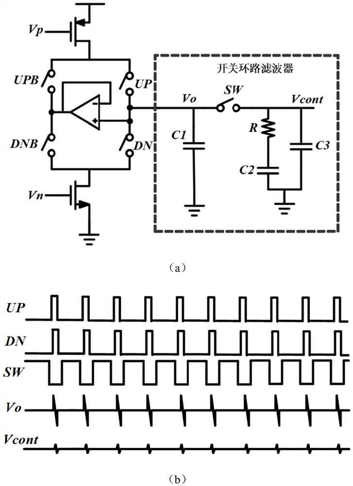
The invention discloses a programmable capacitor array-based frequency band phase-locked loop, which is characterized in that a phase frequency detector circuit is sequentially connected with a charge pump circuit, a switch loop filter and a multiband voltage-controlled oscillator circuit, and the multiband voltage-controlled oscillator circuit is connected with the phase frequency detector circuit through a programmable frequency divider circuit; the phase frequency detector circuit is connected with the switch loop filter through the switch control circuit; reference clock signals clkref and clkdiv generate control signals UP and DN through the phase frequency detector, the charge pump converts a received pulse difference signal into a current signal, then the current signal is converted into a voltage signal through the loop filter to be used for controlling the frequency change of the voltage-controlled oscillator, discrete frequency modulation is achieved by changing the load capacitance, and the frequency of the voltage-controlled oscillator is adjusted. A programmable capacitor array structure is utilized to obtain a frequency output range, and output is fed back to a phase frequency detector through a frequency divider to realize loop locking. Under the condition that the gain of the voltage-controlled oscillator is reduced, low phase noise of the voltage-controlled oscillator is achieved, and meanwhile a wide output frequency range is obtained.

Description

technical field [0001] The invention belongs to the technical field of frequency synthesizers designed for low-power integrated circuits, and in particular relates to a frequency band phase-locked loop based on a programmable capacitor array. Background technique [0002] With the development of the times and the continuous change of science and technology, traditional image sensors can no longer meet daily needs. In recent years, lidar has played an increasingly important role in smartphones, machine vision, autonomous driving and other fields. The current mainstream time-of-flight (ToF) lidar scheme obtains distance information by calculating the round-trip time from the emitted laser pulse to the object to be measured. , Voltage, Temperature, PVT) changes and other requirements are also much higher than other applications. [0003] As a closed-loop automatic control system that can make the phase of the feedback signal track the phase of the input signal, PLL can realize...

Claims


Application Information

Patent Timeline
IPC IPC(8): H03L7/085H03L7/089H03L7/093H03L7/099H03L7/18
CPCH03L7/085H03L7/0891H03L7/093H03L7/0995H03L7/18
Inventor 耿莉陈富伟辛有泽
Owner XI AN JIAOTONG UNIV
Why Eureka
Try Eureka