
Door and window frame deburring device and processing method

A technology for deburring and frame removal, applied in the field of doors and windows, can solve the problems of inability to effectively improve the work efficiency of burr removal, inability to remove burrs, and low work efficiency, so as to ensure convenience and efficiency, and increase the variety of use. and convenience, the effect of improving work efficiency

Pending Publication Date: 2022-06-03
张浩浩
View PDF0 Cites 3 Cited by
  • Summary
  • Abstract
  • Description
  • Claims
  • Application Information

AI Technical Summary

Problems solved by technology

[0003] Since there are two upper and lower corners on the side of the frame of the aluminum alloy window, and the thickness and width of the aluminum alloy windows of different specifications are different, and the conventional burr removal device can only separate the aluminum alloy window during the working process. The corners of the side of the frame are deburred and deburred. It is impossible to perform deburring and deburring on the upper and lower corners of the two sides of aluminum alloy windows of different sizes at the same time, and thus cannot effectively improve the efficiency of deburring. work efficiency, and because the aluminum alloy window will produce a lot of debris during the process of grinding and removing burrs, and the conventional burr removal device cannot automatically and stably collect and process the debris generated by grinding during the working process. Therefore, in order not to affect the follow-up grinding work, the staff also need to perform manual cleaning work, which has low work efficiency and high labor intensity. Therefore, it is necessary to provide a door and window frame deburring device and processing method to meet the needs of users.

Method used


Image

  • Door and window frame deburring device and processing method
  • Door and window frame deburring device and processing method
  • Door and window frame deburring device and processing method

Examples


Embodiment

[0043] In order to make the objectives, technical solutions and advantages of the present invention clearer, the embodiments of the present invention will be further described in detail below with reference to the accompanying drawings.

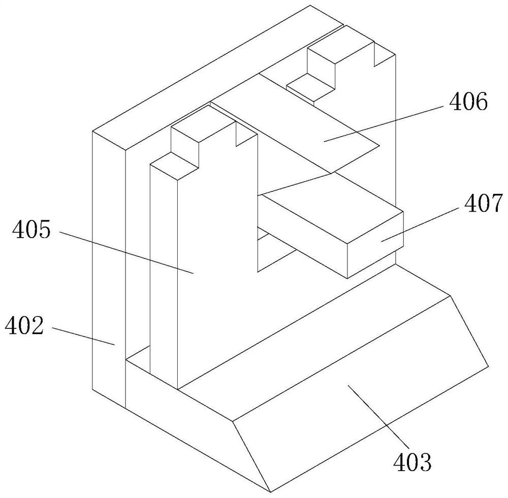
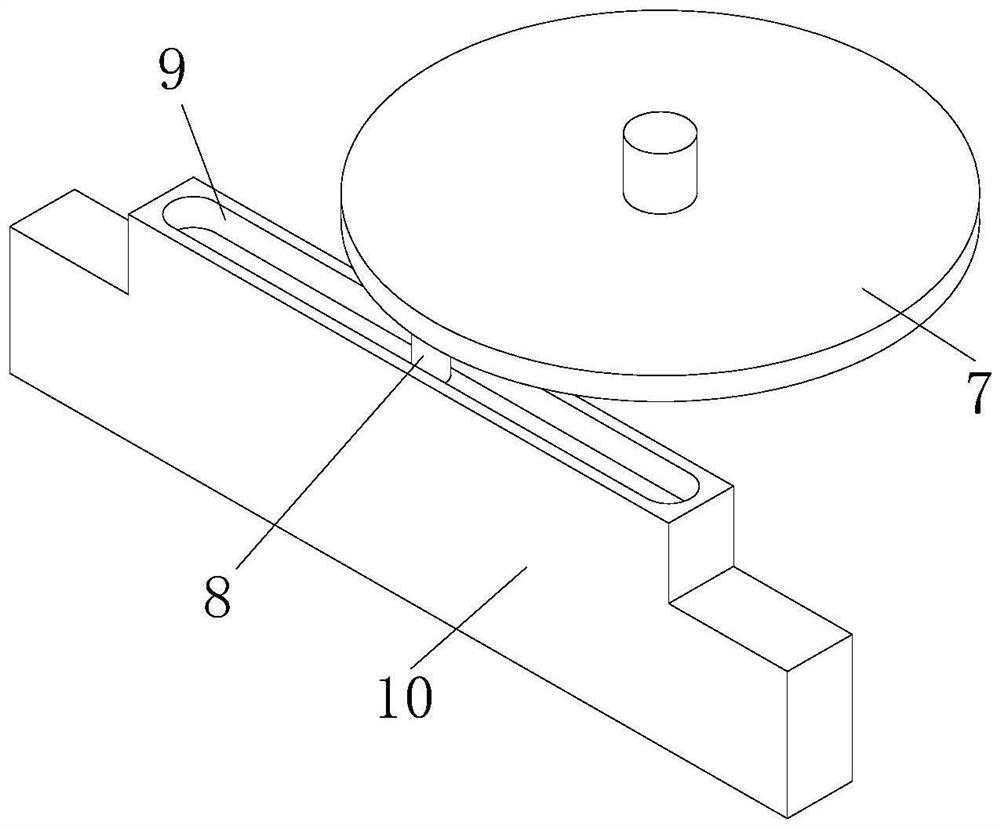
[0044] like Figure 1-13 As shown, a door and window frame deburring device includes a fixed base 1, a support rod 2 is welded and fixed on the fixed base 1, a worktable 3 is welded and fixed on the top of the support rod 2, and an adaptive grinding mechanism 4 is installed on the worktable 3 , a servo motor 6 is welded and fixed on the bottom end surface of the fixed base 1, a rotating plate 7 is welded and fixed on the output shaft of the servo motor 6, and a first limit rod 8 is welded and fixed on the rotating plate 7, and the first limit rod 8 is limited The position sliding connection is in the first sliding groove 9, the first sliding groove 9 is opened at the bottom of the mounting plate 10, the mounting plate 10 is limited slidingly ...


PUM


Abstract

The invention belongs to the field of doors and windows, and particularly relates to a door and window frame deburring device and a processing method.The door and window frame deburring device comprises a fixed base, a supporting rod is fixedly welded to the fixed base, a workbench is fixedly welded to the top of the supporting rod, and a self-adaptive grinding mechanism is installed on the workbench; a servo motor is fixedly welded to the bottom end face of the fixed base, a rotating plate is fixedly welded to an output shaft of the servo motor, the first sliding groove is formed in the bottom of a mounting plate, the mounting plate is slidably connected into a limiting groove in a limited mode, the limiting groove is formed in the workbench, and an adsorption connecting assembly is mounted on the mounting plate. The problems that an existing burr removing device cannot conduct burr grinding and removing work on the upper corner and the lower corner of the two side edges of the aluminum alloy windows of different specifications and sizes at the same time, and meanwhile scraps generated by grinding cannot be automatically and stably collected and treated are solved.

Description

technical field [0001] The invention relates to the field of doors and windows, in particular to a door and window frame deburring device and a processing method. Background technique [0002] Aluminum alloy window is a window with frame and fan structure made of aluminum alloy building profiles. Aluminum alloy window has beautiful appearance, sealing and high strength, and is widely used in the field of construction engineering. The profile is cut by size. Since a large number of burrs will remain at the port of the cut profile, in order to prevent the burr from damaging the operator in the subsequent processing process, it is necessary to use a deburring device to perform burr grinding and removal work on the aluminum alloy window, and some burrs There are some problems with the clearing device: [0003] Since there are two upper and lower corners on the side of the frame of the aluminum alloy window, and the thickness and width of the aluminum alloy windows of different ...

Claims


Application Information

Patent Timeline
Patent Type & Authority Applications(China)
IPC IPC(8): B24B9/04B24B27/00B24B55/12B24B41/06B24B55/00B24B41/02B24B27/02
CPCB24B9/04B24B27/0076B24B55/12B24B41/06B24B55/00B24B41/02B24B27/02Y02P70/10
Inventor 张浩浩
Owner 张浩浩
Learn More