
Diversion type low-flow-resistance heat pipe heat exchanger

A heat pipe heat exchanger, low flow resistance technology, applied in indirect heat exchangers, heat exchanger shells, heat exchange equipment, etc. Increased corrosion and other issues

Pending Publication Date: 2022-05-27
王剑
View PDF0 Cites 0 Cited by
  • Summary
  • Abstract
  • Description
  • Claims
  • Application Information

AI Technical Summary

Problems solved by technology

[0002] At present, heat pipe heat exchanger technology is used in the utilization of flue gas waste heat in coal-fired power plants, coal chemical industry, cement plants, blast furnace gas and other fields. Rich in NH4HSO4, the application of traditional wall heat exchanger technology in this field has encountered technical problems such as sticky ash plugging and low-temperature corrosion. Although heat pipe heat exchanger technology has shown good characteristics in solving the above problems, However, at present, in the field of flue gas waste heat utilization, whether it is a heat pipe low-pressure economizer, a heat pipe air preheater, or a rotary air preheater low-temperature section using heat pipe technology, the heat pipe on the flue gas side of the heat exchanger adopts The most is a circular tube structure. In order to reduce the flow resistance of the flue gas side and the sticky ash blockage, although the flue gas side adopts a smooth tube measure, it has been verified by actual operation that when the flue gas side has a large diameter and the heat exchanger tube When the pitch design is small, it will still lead to large flow resistance on the flue gas side and aggravated ash blockage, especially when a heat pipe with a larger diameter is used to increase the axial heat transfer power of a single heat pipe, the resistance increase is particularly obvious
Although part of the flue gas flow resistance can be weakened when the heat exchanger is designed with a larger tube pitch, it is necessary to ensure that the heat exchange power of the heat pipe heat exchanger cannot be reduced, that is, the number of heat pipes cannot be reduced, and the actual technical transformation is implemented. Adapt to the inherent space of the existing equipment, and after the flue gas side adopts the light pipe, the convective heat transfer coefficient outside the pipe is greatly reduced. In order to ensure the heat transfer, the number of heat pipes must be increased, which brings two problems. One is that it can be used The space is insufficient, and the second is that the heat transfer and heat transfer power cannot meet the requirements. How to solve this contradiction, smoothly apply the heat pipe technology to the heat exchange of low-temperature flue gas in coal-fired power plants, and solve the problems existing in the waste heat recovery and utilization process of the original flue gas The problems of sticky ash blockage, increasing flue gas flow resistance, and insufficient pressure head of fans will be problems that need to be solved

Method used


Image

  • Diversion type low-flow-resistance heat pipe heat exchanger
  • Diversion type low-flow-resistance heat pipe heat exchanger
  • Diversion type low-flow-resistance heat pipe heat exchanger

Examples


Embodiment Construction

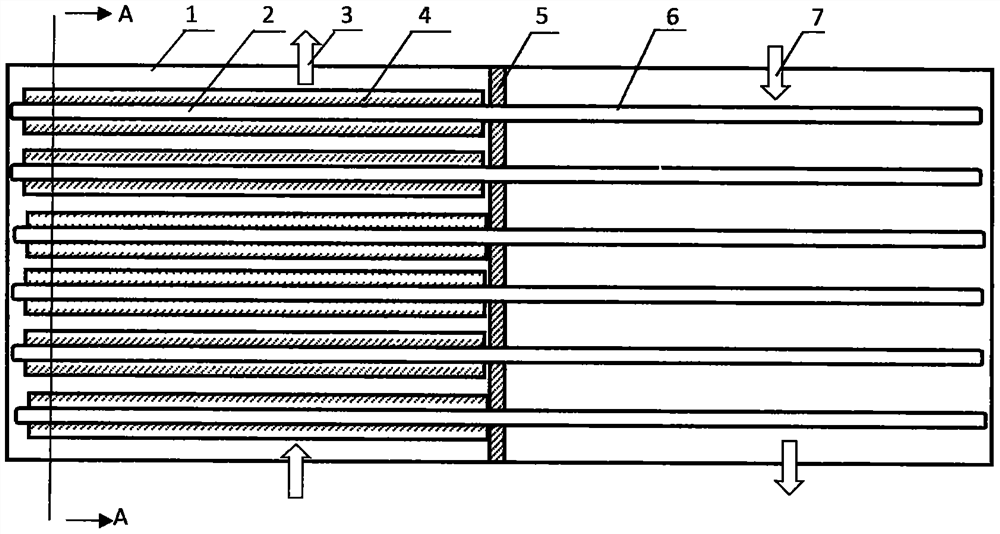
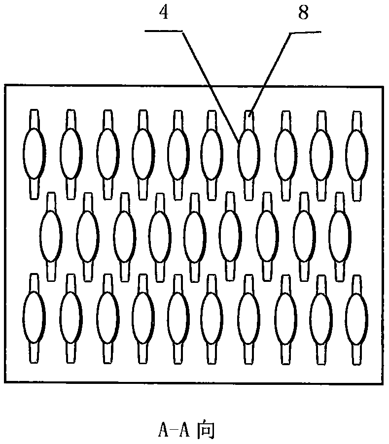
[0024] Reference attached Figure 1 attach Figure 2 attach Figure 3 attach Figure 4 A diversion type low-flow resistance heat pipe heat exchanger shown comprises a heat exchanger box 1, a diversion type low-flow resistance heat pipe 2, a hot end fluid channel 3, a hot end 4, a tube plate 5, a cold end 6, a cold end fluid channel 7, a hot end diversion fin 8. When specifically implemented, the heat pipe hot end 4 is processed into an oval shape, and then the diversion fin 8 symmetrically welded to the hot end 4, in accordance with the requirements of the heat pipe production technology to produce a complete diversion type low flow resistance heat pipe 2, so far, including the hot end 4 and cold end 6 of the diversion type low flow resistance heat pipe is completed, and then the diversion type low flow resistance heat pipe 2 is assembled into the tube plate 5 composed of a heat exchanger bundle assembly according to the designed pipe arrangement, and this assembly is hoisted to the h...


PUM


Abstract

A flow guide type low-flow-resistance heat pipe heat exchanger comprises a heat pipe heat exchanger box body, a pipe plate and a flow guide type low-flow-resistance heat pipe bundle.

Description

Technical field [0001] The present invention relates to the application of heat pipe technology in the field of flue gas waste heat recovery and utilization, specifically a diversion type low-flow resistance heat pipe heat exchanger. Background [0002] At present, the heat pipe heat exchanger technology in coal-fired power plants, coal chemical industry, cement plants, blast furnace gas and other fields of flue gas waste heat utilization, due to the improvement of environmental emission standards, the system out of stock using SCR process, there is ammonia escape, the original flue gas is rich in NH4HSO4, the traditional wall heat exchanger technology in this field of application process encountered viscous ash blockage, low temperature corrosion increasing and other technical problems, although the heat pipe heat exchanger technology in the process of solving the above problems, showing good characteristics, but, currently in the field of flue gas waste heat utilization , wheth...

Claims


Application Information

Patent Timeline
IPC IPC(8): F23J15/06F28D15/02F28F1/12F28F9/02F28F9/18
CPCF28D15/0275F23J15/06F28F9/02F28F9/18F28F1/12Y02E20/30
Inventor 不公告发明人
Owner 王剑
Learn More