
High-efficiency compact heat exchanger with vertical cross microchannel

A micro-channel, compact technology, applied in the field of heat exchange, to achieve the effect of small size, good economy and high heat exchange power of heat exchanger

Active Publication Date: 2017-05-10
NUCLEAR POWER INSTITUTE OF CHINA
View PDF5 Cites 0 Cited by
  • Summary
  • Abstract
  • Description
  • Claims
  • Application Information

AI Technical Summary

Problems solved by technology

However, limited by gasket sealing methods and other traditional technologies, it is difficult for plate heat exchangers to make breakthroughs in the field of high temperature (above 500°C) and high pressure (above 20MPa), and therefore it is difficult for plate heat exchangers to be used in supercritical fluid energy conversion systems. Applied in medium (high temperature and high pressure conditions)

Method used


Image

  • High-efficiency compact heat exchanger with vertical cross microchannel
  • High-efficiency compact heat exchanger with vertical cross microchannel
  • High-efficiency compact heat exchanger with vertical cross microchannel

Examples


Embodiment 1

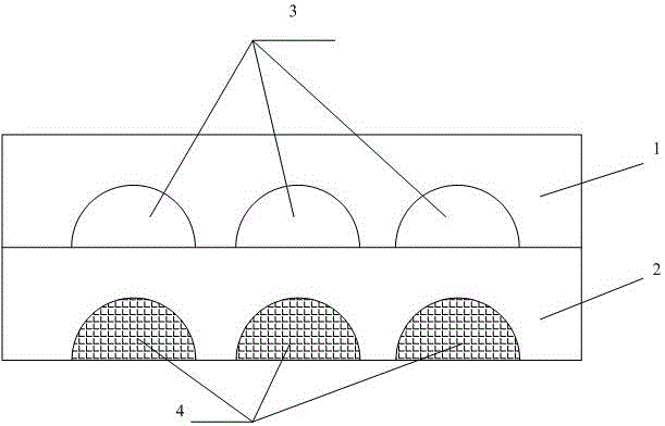
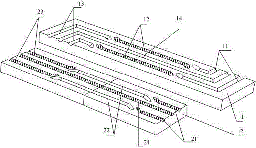
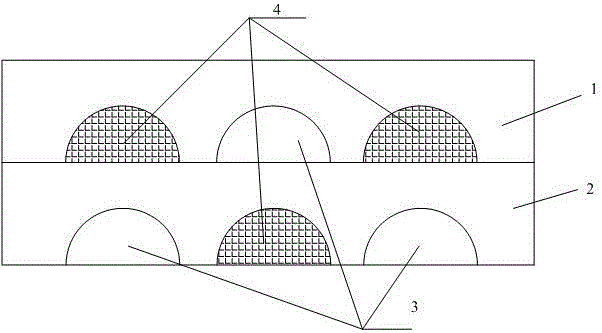
[0028] like Figure 1-Figure 3 Shown: vertical cross microchannel high-efficiency compact heat exchanger, including at least 2 stacked flow plates, the two adjacent flow plates are respectively upper flow plate 1 and lower flow plate 2, and at least 2 fluid channels, upper flow plate 1 and the downstream plate 2 are provided with heat exchange channels, the heat exchange channel of the upper plate 1 includes at least one first-type flow channel, the first-type flow channel includes the first-type flow channel inlet section 11, the first-type The middle section of the flow channel 12, the outlet section of the first type of flow channel 13, the heat exchange flow channel of the lower flow plate 2 includes at least one second type of flow channel, the second type of flow channel includes the inlet section of the second type of flow channel The intermediate section 22 of the type flow channel, the outlet section 23 of the second type flow channel, the inlet section 11 of the firs...

Embodiment 2

[0032] like figure 2 , image 3 Shown:

[0033] The heat exchange channels of the upper flow plate 1 include two first-type flow channels and one third-type flow channel 14, and the heat exchange channels of the lower flow plate 2 include two second-type flow channels and one fourth-type flow channel twenty four. The first type of flow channel includes the first type of flow channel inlet section 11, the first type of flow channel middle section 12, the first type of flow channel outlet section 13, and the second type of flow channel includes the second type of flow channel inlet section 21, the second type of flow channel The intermediate section 22 of the type flow channel, the outlet section 23 of the second type flow channel, the inlet section 11 of the first type flow channel communicates with the outlet section 13 of the first type flow channel through the middle section 22 of the second type flow channel, The section 21 communicates with the outlet section 23 of the...


PUM


Abstract

The invention discloses a high-efficiency and compact heat exchanger with vertical crossing microchannels, which comprises at least two flow plates stacked together, and the two adjacent flow plates are respectively an upper flow plate and a lower flow plate, and at least two fluid channels, the upper flow plate and the lower flow plate Heat exchange channels are arranged in the downstream plate, and the heat exchange channel of the upper plate includes at least one first-type flow channel, the first-type flow channel includes the inlet section of the first-type flow channel, the middle section of the first-type flow channel, The outlet section of the first type of flow channel, the heat exchange flow channel of the down flow plate includes at least one second type of flow channel, the second type of flow channel includes the inlet section of the second type of flow channel, the middle section of the second type of flow channel, the second type of flow channel The outlet section of the flow channel, the inlet section of the first type of flow channel communicates with the outlet section of the first type of flow channel through the middle section of the second type of flow channel, and the inlet section of the second type of flow channel connects with the second type of flow channel through the middle section of the first type of flow channel The exit section of the road is connected. Through the design of the inlet and outlet flow channels of the heat exchanger, part of the flow channels of the upper and lower boards is opened to achieve the purpose of realizing the three-dimensional fluid arrangement of the hot and cold runners in the printed circuit board.

Description

technical field [0001] The invention relates to the technical field of heat exchange, in particular to an interchange type microchannel high-efficiency and compact heat exchanger. Background technique [0002] Energy power is one of the important pillars of the development of human science and technology, and the heat exchanger is an essential key core equipment in this field. With the advancement of heat exchange technology, people have invented and manufactured a wide variety of heat exchangers, such as shell-and-tube heat exchangers, tube-sheet heat exchangers, plate-fin heat exchangers, and plate-shell heat exchangers. , plate heat exchangers, etc., each heat exchanger has roughly experienced three stages of development: smooth surface, two-dimensional vortex generation design, and three-dimensional vortex generation design. For nearly a century, plate heat exchangers have held a monopoly on high heat transfer efficiency. However, limited by gasket sealing methods and ...

Claims


Application Information

Patent Timeline
Patent Type & Authority Patents(China)
IPC IPC(8): F28D9/02F28F3/00
CPCF28D9/00F28F3/00
Inventor 刘生晖黄彦平王俊峰郎雪梅赵大卫刘光旭
Owner NUCLEAR POWER INSTITUTE OF CHINA
Learn More