Laser additive manufacturing isotropic scanning method for scanning galvanometer

A laser additive and isotropic technology, applied in the field of additive manufacturing, can solve problems such as anisotropy of tissue properties, and achieve the effects of reducing residual stress, reducing cumulative effect, and increasing the existence time of molten pool

Pending Publication Date: 2022-05-27
ZHEJIANG UNIV OF TECH
View PDF0 Cites 1 Cited by
  • Summary
  • Abstract
  • Description
  • Claims
  • Application Information

AI Technical Summary

Problems solved by technology

[0005] The purpose of the present invention is to solve the problem of the anisotropy of tissue properties in the laser additive manufacturing process of the scanning galvanometer, and propose a scanning method for synchronous remelting of the laser additive manufacturing of the scanning galvanometer, through which the increase can be reduced. The residual stress and porosity inside the material manufacturing layer can reduce the cumulative effect of roughness between layers, and improve the surface quality and mechanical properties isotropy

Method used


Image

  • Laser additive manufacturing isotropic scanning method for scanning galvanometer
  • Laser additive manufacturing isotropic scanning method for scanning galvanometer
  • Laser additive manufacturing isotropic scanning method for scanning galvanometer

Examples


Embodiment 1

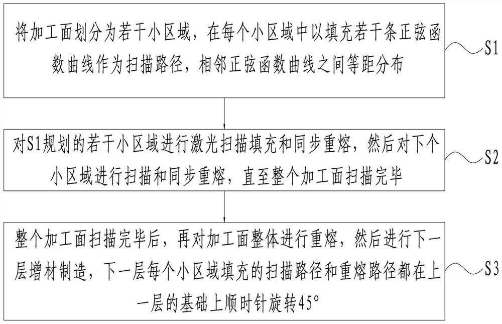
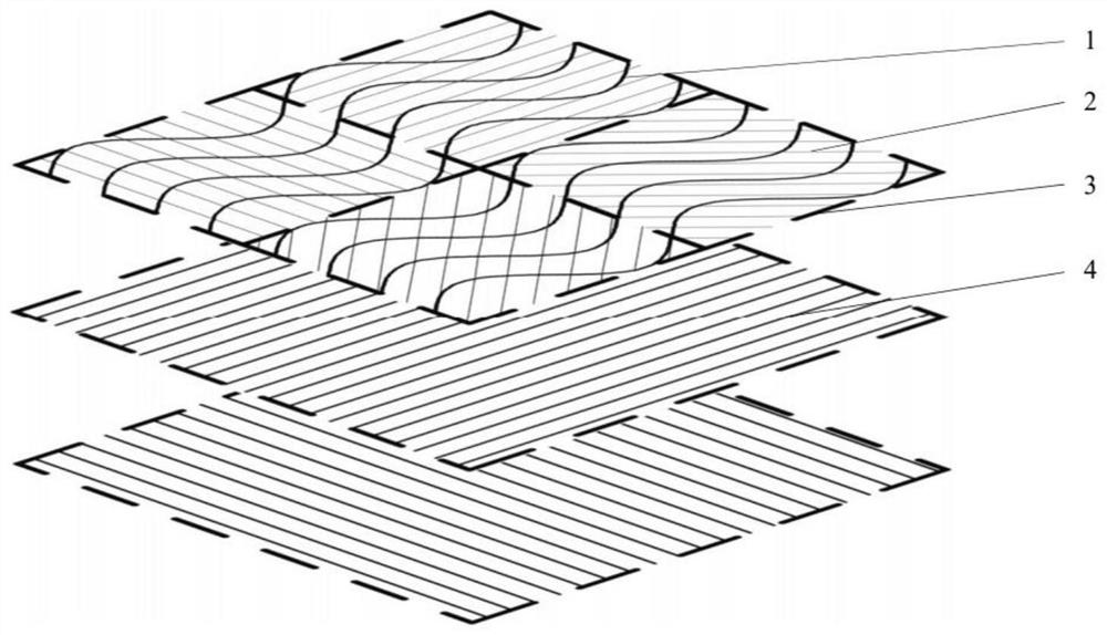
[0020] A laser additive manufacturing isotropic scanning method for scanning galvanometers is adopted, which includes the following steps:

[0021] (1) Set the size of the processing surface to be 100×100mm, and the size of each small area to be 4×4mm;

[0022] (2) A small area is evenly filled with a sine curve as the scanning path. The amplitude of the sine function curve is 1mm, the period is 2π, and the initial phase angle is 0°. Two adjacent sinusoids are equally spaced, with a distance of 0.03mm; a straight line is uniformly filled as the remelting path, and two adjacent lines are equally spaced, with a distance of 0.03mm. The remelting path is perpendicular to the axis of the scanning path along the period direction;

[0023] (3) Carry out laser scanning filling and synchronous remelting along the scanning path and remelting path planned in step (2), the laser power is 600W, and the scanning speed is 500mm / s; Melting, the two remelting paths are perpendicular to each ...

Embodiment 2

[0025] The invention is used to repair the cavitation part of the steam turbine blade, and the mild cavitation area of ​​the blade is polished and the surface oil stains are removed with acetone.

[0026] Perform penetrant testing on the area to be repaired to confirm that the cavitation area is completely removed.

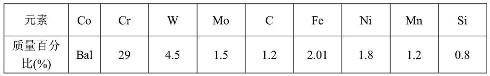
[0027] A Co-based alloy powder is selected as the repair material, and its composition is as follows:

[0028]

[0029] The area of ​​the blade to be repaired is a curved surface, and a 6% sodium silicate solution is used as the binder. After mixing with the alloy powder at a weight ratio of 1:5 to a paste, smear it on the area to be repaired and compact it, and then add a 0.2mm feeler gauge. Spread it on both sides of the powder, use a spatula to smooth the powder, and let it sit for 5 minutes to wait for the adhesive to dry.

[0030] Adjust the focal length of the galvanometer laser additive manufacturing system, divide the area to be repaired into several 5...


PUM


Abstract

The invention discloses a laser additive manufacturing isotropic scanning method for a scanning galvanometer, which comprises the following steps of: dividing a processing surface into a plurality of small areas, filling a plurality of sine function curves in each small area as a scanning path, and equidistantly distributing adjacent sine function curves; s2, laser scanning filling and synchronous remelting are conducted on the multiple small areas planned in the S1, and then scanning and synchronous remelting are conducted on the next small area till the whole machining face is scanned; and after the whole machined surface is scanned, the whole machined surface is remelted, then additive manufacturing of the next layer is carried out, and the scanning path and the remelting path for filling each small area of the next layer are clockwise rotated by 45 degrees on the basis of the upper layer. According to the method, through curve path scanning and synchronous remelting, due to the fact that the grain growth direction is disturbed, grains are arranged disorderly, and the overall mechanical property of the additive manufacturing layer tends to be isotropic.

Description

technical field [0001] The invention belongs to the field of additive manufacturing, and particularly relates to a laser additive manufacturing isotropic scanning method for scanning a galvanometer. Background technique [0002] Additive Manufacturing (AM) is the opposite of traditional subtractive processing. It uses high-energy-density lasers to melt materials point by point, accumulate them layer by layer, and form them directly. Since its emergence, additive manufacturing technology has attracted widespread attention due to its advantages of short processing cycle, high production efficiency, and highly flexible production. [0003] The emergence of the high-power scanning galvanometer system has greatly improved the laser processing speed and production efficiency. The deflection of the X and Y reflected beams is driven by the computer-controlled mechanical device to realize the movement of the laser beam within the working range, and follow the established scanning rou...

Claims


Application Information

Patent Timeline
Patent Type & Authority Applications(China)
IPC IPC(8): B22F10/28B22F10/366B22F10/364B22F10/85B22F10/50B33Y10/00B22F5/04
CPCB22F10/28B22F10/366B22F10/364B22F10/85B22F10/50B33Y10/00B22F5/04Y02P10/25
Inventor 陈智君张群莉姚建华陈和超
Owner ZHEJIANG UNIV OF TECH
Why Eureka
Try Eureka