Throwing type radiation detector

A radiation detector and radiation detection technology, applied in the field of throwing radiation detectors, can solve the problems of incorrect wireless antenna pointing, inability to transmit and return detection data, etc., to achieve a high level of stability and directional directivity, super strong The effect of anti-beating ability and strong sealing performance

Pending Publication Date: 2022-04-26
中国兵器装备集团自动化研究所有限公司
View PDF0 Cites 0 Cited by
  • Summary
  • Abstract
  • Description
  • Claims
  • Application Information

AI Technical Summary

Problems solved by technology

[0005] The technical problem to be solved by the present invention is the serious problem that the detection data cannot be transmitted and sent back due to the incorrect pointing of the wireless antenna of the detector when the common radiation detector in the prior art is thrown by a drone

Method used


Image

  • Throwing type radiation detector
  • Throwing type radiation detector
  • Throwing type radiation detector

Examples


Embodiment 1

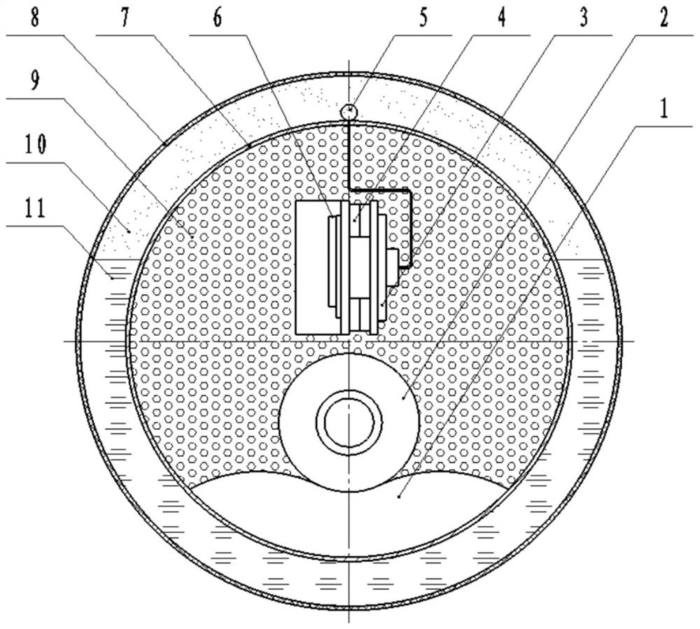
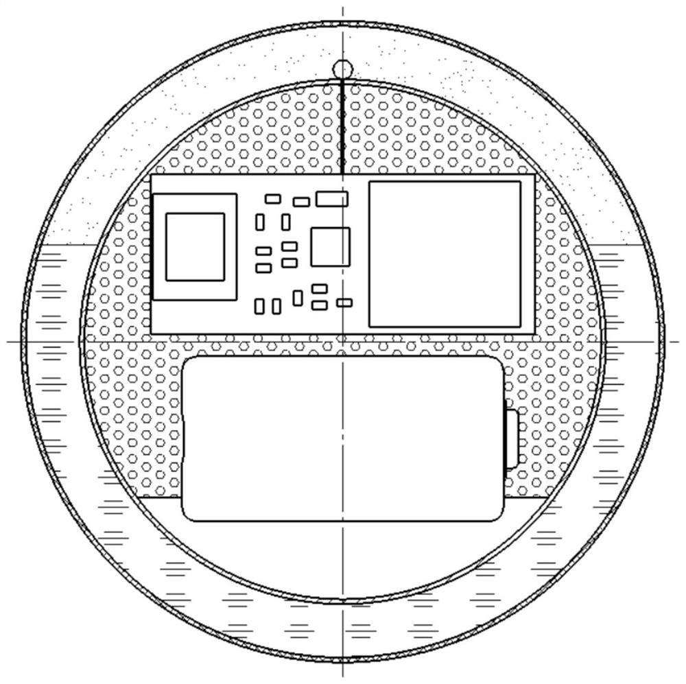
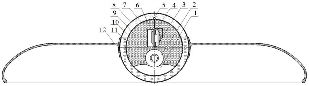
[0049] Such as Figure 1 to Figure 3 As shown, a throwing type radiation detector of the present invention includes a spherical inner casing 7 and a spherical outer casing 8, and the spherical inner casing 7 is arranged inside the spherical outer casing 8;

[0050] The spherical inner casing 7 is provided with a radiation detection module, and the radiation detection module is used to complete radiation detection and data transmission tasks in radioactive areas within a predetermined time;

[0051] The lower part between the spherical outer shell 8 and the spherical inner shell 7 is provided with a first medium 11, and the upper part is provided with a second medium 10, and the radiation detection module is always floating in the first medium 11 and points to a set direction , and the upper part faces upwards, so that the antenna of the radiation detection module always points to the Beidou satellite. During implementation, the first medium 11 is pure water, and the second me...

Embodiment 2

[0070] Such as Figure 1 to Figure 3 As shown, the difference between this embodiment and Embodiment 1 is that the throwing radiation detector of the present invention is applicable to the following throwing and distributing methods:

[0071] The first method of throwing and distributing: UAVs are airlifted to the radiation site for aerial throwing and distributing, forming a huge radiation detection network that can cover huge radioactively polluted areas, detect radioactive data in radioactively polluted areas, and transmit them wirelessly Data is transmitted back to command for use by radiation detection personnel.

[0072] The second method of throwing and distributing: flying saucer ejector spreading. When the throwing radiation detector is distributed by flying saucer ejector, it is formed by installing a spherical throwing radiation detector in a butterfly shell 12. Yes, it is more suitable for radioactively contaminated areas with relatively small areas and low radioa...


PUM


Abstract

The invention discloses a throwing type radiation detector which can collect data of radiation intensity and range of places such as a nuclear explosion area and a nuclear leakage accident area and transmit the data to the outside of a nuclear pollution area so as to provide a basis for calibrating the radiation intensity of the nuclear pollution area and delimiting the range of the nuclear pollution area. The throwing type radiation detector comprises a spherical outer shell, a spherical inner shell, a radiation detection module, a Beidou antenna and the like; a first medium-pure water is arranged at the lower part between the spherical outer shell and the spherical inner shell, a second medium-air is arranged at the upper part between the spherical outer shell and the spherical inner shell, and the antenna and the radiation detection module wrapped in the spherical inner shell float in the pure water. According to the throwing type radiation detector, the antenna of the radiation detection module always points to the Beidou satellite no matter unmanned aerial vehicle throwing or other throwing modes are adopted, and no matter the detector is thrown in desert, a partition wall, a mountain land or a grassland, so that the serious problem that detection data cannot be transmitted due to incorrect antenna pointing is effectively avoided.

Description

technical field [0001] The invention relates to the field of surface radioactive pollution detection, in particular to a throwing type radiation detector. Background technique [0002] The harm of radioactive radiation to living things is very serious. Radiation injury includes acute injury and chronic injury. If a person is exposed to a large dose of X-rays, gamma rays and neutrons in a short period of time, acute injuries will occur. Mild cases have symptoms such as hair loss and infection. When the dose is larger, gastrointestinal damage such as diarrhea and vomiting may occur. Under extremely high doses of radiation, damage to the central nervous system occurs until death. High-intensity radiation can burn the skin, cause leukemia and various cancers, destroy human reproductive skills, and in severe cases can cause death in a short period of time. [0003] Nuclear explosion areas, nuclear leakage accident areas, nuclear fuel mining areas and other places have extrem...

Claims


Application Information

Patent Timeline
Patent Type & Authority Applications(China)
IPC IPC(8): G01T1/169G01T7/00G08C17/02
CPCG01T1/169G01T7/00G08C17/02
Inventor 温江波姚飞侯鑫魏嫣然廖鹏汪宇李林珊
Owner 中国兵器装备集团自动化研究所有限公司
Why Eureka
Try Eureka