
Time synchronization safety monitoring method and system based on long short-term memory network

A technology of long and short-term memory and security monitoring, applied in the time-frequency field, can solve the problems of low accuracy and poor anti-interference, and achieve the effect of high accuracy, wide application range, and avoiding false identification of system security status.

Pending Publication Date: 2022-04-22
NO 30 INST OF CHINA ELECTRONIC TECH GRP CORP
View PDF0 Cites 0 Cited by
  • Summary
  • Abstract
  • Description
  • Claims
  • Application Information

AI Technical Summary

Problems solved by technology

[0005] Aiming at the problems of poor anti-interference and low accuracy of traditional time synchronization security monitoring methods, the present invention proposes a time synchronization security monitoring method and system based on long-term and short-term memory networks, which does not require statistical analysis of the development and change characteristics of the system clock, and can eliminate The impact of environmental changes and noise interference on the accuracy of attack identification to improve the accuracy of time synchronization attack identification

Method used


Image

  • Time synchronization safety monitoring method and system based on long short-term memory network
  • Time synchronization safety monitoring method and system based on long short-term memory network
  • Time synchronization safety monitoring method and system based on long short-term memory network

Examples


Embodiment 1

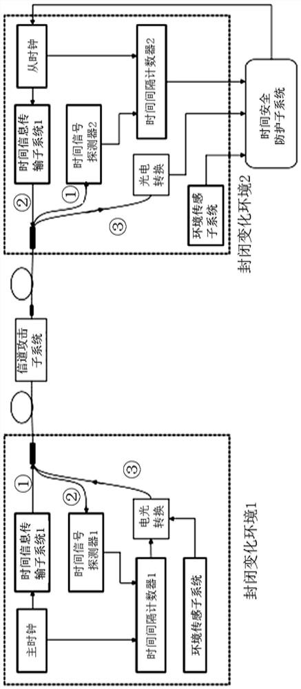
[0042] Embodiment 1 (deployment after laboratory environment training)

[0043] In order to illustrate the specific implementation manner of the present invention, the detailed description will be given below in conjunction with the accompanying drawings. Build a time synchronization security monitoring system in the experimental environment, such as figure 2 shown. In order to prevent changes in the key characteristics of the system relative to the laboratory environment caused by the deployment process, the accuracy of system attack recognition after the migration of the pre-deployment-trained long-short-term memory network to the post-deployment system is reduced. The system used for training in the laboratory environment is as consistent as possible with the actual deployed system for attack identification. The pre-deployment system is trained, and the trained and mature system is deployed on the spot. After the deployment is completed, the system directly judges the sy...

Embodiment 2

[0068] Embodiment 2 (Training under the real environment after deployment)

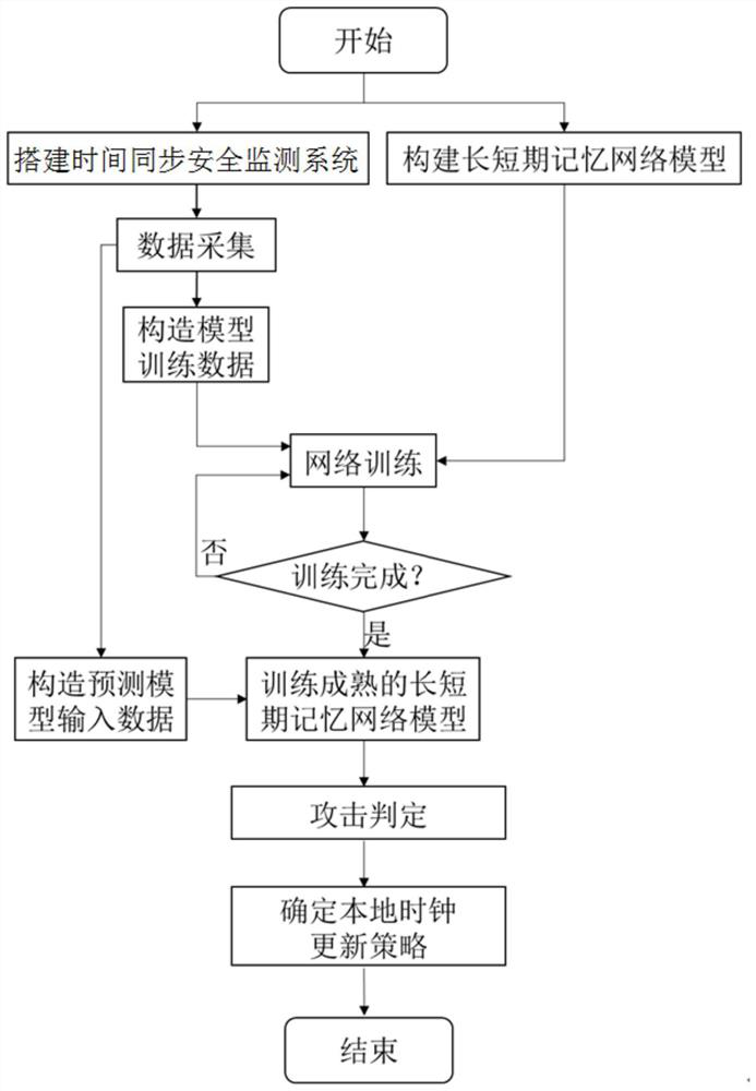
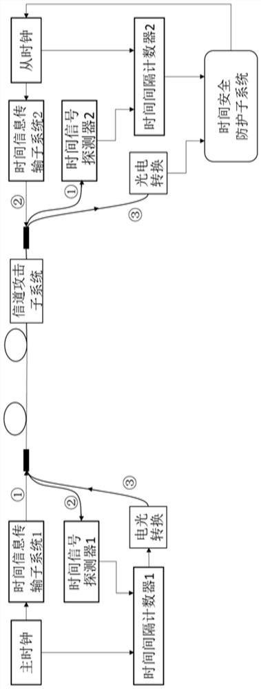
[0069] In order to illustrate the specific implementation manner of the present invention, the detailed description will be given below in conjunction with the accompanying drawings. Deploy a time synchronization security monitoring system for time synchronization attack identification training in the field, such as image 3 shown. After the deployment is completed, the long-short-term memory network is trained according to the data collected after field deployment. A mature system such as Figure 4 As shown, the system security status can be judged according to the data collected on site. System construction and processing methods such as figure 1 shown.

[0070] Step S1: Build a time-synchronized security monitoring system for training after deployment, such as image 3 shown. The time synchronization safety monitoring system includes a master clock, a slave clock, a time information transmis...

Embodiment 3

[0094] Embodiment 3 (environmental training during the experiment first, and then on-site intensive training after deployment)

[0095] In order to illustrate the specific implementation manner of the present invention, the detailed description will be given below in conjunction with the accompanying drawings. First, build a time-synchronized security monitoring system for long-short-term memory network training in a laboratory environment, such as figure 2 As shown, the long-short-term memory network is trained by obtaining data in the laboratory environment; after the training is mature, the time-synchronized security monitoring system is deployed in the field, such as image 3 As shown, according to the data collected in the field, the long-short-term memory network migrated from the laboratory is intensively trained until the network training is mature; after that, the mature time-synchronized security monitoring system is trained on-site, such as Figure 4 As shown, it ...


PUM


Abstract

The invention discloses a time synchronization safety monitoring method and system based on a long short-term memory network, and the method comprises the steps: S1, building a time synchronization safety monitoring system, the system comprises a master clock, a slave clock, a time information transmission subsystem, a channel attack subsystem, a time information acquisition subsystem, a time security protection subsystem and an environment sensing subsystem, s2, acquiring basic data for training the time safety protection subsystem; s3, establishing a long short-term memory network on the time security protection subsystem, and training the long short-term memory network based on the constructed training data set; and S4, performing on-site deployment by the time synchronization safety monitoring system, and migrating the well-trained long and short-term memory network model before deployment to an on-site deployment environment for reinforcement learning. The method can eliminate the influence of environment change and noise interference on the attack recognition accuracy, and improves the time synchronization attack recognition accuracy.

Description

technical field [0001] The invention relates to the field of time-frequency technology, in particular to a time synchronization safety monitoring method and system based on a long-short-term memory network. Background technique [0002] High-precision time synchronization technology has extensive and important applications in basic science, astronomical observation, positioning and navigation, national defense security, communication, and finance. The time transfer synchronization technology based on optical fiber links has gradually developed into a new type of time synchronization technology due to its advantages of low loss and high stability. [0003] At present, time synchronization methods based on optical fiber links can be divided into one-way method transmission and two-way method transmission. In applications where the transfer distance is long and the transfer accuracy is high, the two-way time transfer method is more suitable. The prerequisite for the two-way t...

Claims


Application Information

Patent Timeline
IPC IPC(8): H04J3/06H04J14/02H04L9/40G06N3/04G06N3/08
CPCH04J3/0658H04J14/0227H04L63/1441G06N3/08G06N3/044Y04S40/20
Inventor 胡金龙徐兵杰李扬黄伟马荔杨杰盘艳罗钰杰周创
Owner NO 30 INST OF CHINA ELECTRONIC TECH GRP CORP
Learn More