
Epoxy glue potting process method for tail-cover-free electric connector cable

A technology of electrical connectors and process methods, applied in the direction of connection, circuit/collector parts, circuits, etc., can solve the problems of low fatigue strength, long production cycle, weak bonding performance of potting glue, etc., and achieve fatigue strength. Large, short production cycle, high bonding performance and strength

Pending Publication Date: 2022-03-22
SHANGHAI INST OF SPACE POWER SOURCES
View PDF0 Cites 0 Cited by
  • Summary
  • Abstract
  • Description
  • Claims
  • Application Information

AI Technical Summary

Problems solved by technology

However, there are the following defects: PTFE products require specific molds for processing, the molds are not environmentally friendly, the processing is complicated, the production cycle is long, and it cannot adapt to the problem of potting electrical connectors with many varieties and large batches.
The solubility of silicone oil to absolute ethanol is poor, and it is difficult to clean the silicone oil after potting, and the silicone oil needs to be manually applied to the mold. The uniformity of the application depends on the skill level of the operator, and it is difficult to guarantee the efficiency and quality of the application. Touching other objects will lead to local silicone oil loss and demoulding failure
The traditionally used potting glue is generally silicone rubber or E51 epoxy glue. The strength of ordinary silicone rubber is low, and it cannot maintain the bonding performance under harsh mechanical environments. However, E51 epoxy glue has a large curing stress and cannot be used under harsh temperature environments. Cracks are prone to occur under the surface, resulting in the problems of weak bonding performance and low fatigue strength of the potting glue

Method used


Image

  • Epoxy glue potting process method for tail-cover-free electric connector cable
  • Epoxy glue potting process method for tail-cover-free electric connector cable
  • Epoxy glue potting process method for tail-cover-free electric connector cable

Examples


Embodiment 1

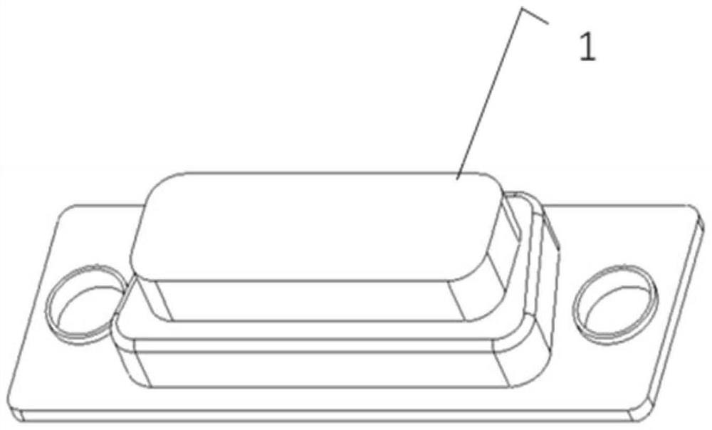
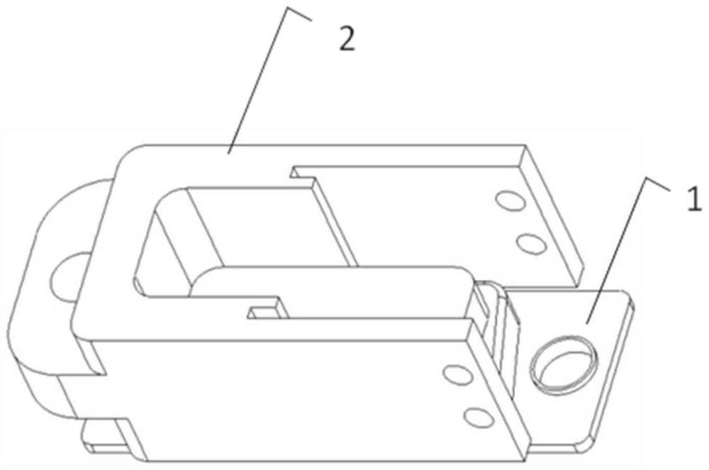
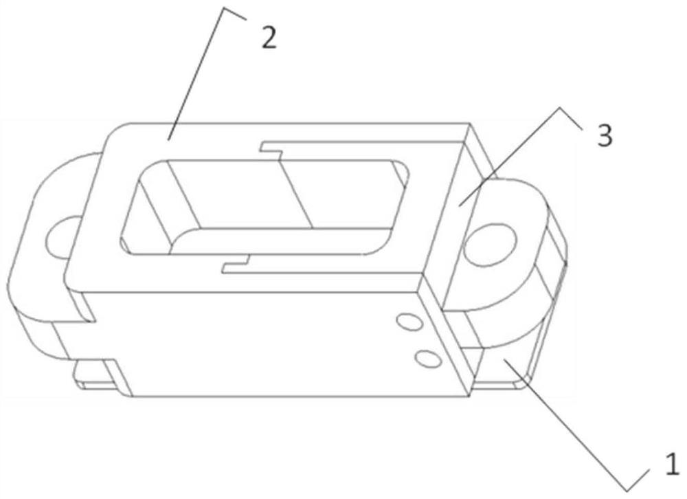
[0039] In order to facilitate environmental protection and biodegradation, polylactic acid is used as the material of the potting mold. Such as figure 1 As shown, the potting mold is designed according to the shape of the electrical connector 1 to be potted, including such as Figure 4 As shown on the left die 2 and as Figure 5 The right mold 3 shown has a matching snap-fit ​​structure, can be combined into a potting mold, and is easy to disassemble. Use the 3D printing manufacturing method to print the left mold 2 and the right mold 3 respectively. After the left mold 2 and the right mold 3 are assembled and installed, they can be fixed on the outer surface with polyimide tape, or can be fixed with GD414 silicone rubber. Prepare the release paint, the composition of the release paint includes 7385 polyurethane varnish, 7312 polyurethane curing agent, and butyl acetate, and the mass ratio is 6:1:2; the release paint is evenly placed in the atomizing spray gun, and the atomi...

Embodiment 2

[0042] Such asfigure 1 As shown, the potting mold is designed according to the shape of the electrical connector 1 to be potted, and the potting mold includes such as Figure 4 As shown on the left die 2 and as Figure 5 The right mold 3 shown uses the 3D printing manufacturing method to print the potting mold. The material of the potting mold is polylactic acid. After the left mold and the right mold are made, polyimide tape is pasted on the outer surface to connect the two together. It can also be glued together by GD414 silicone rubber; prepare the release paint, the composition of the release paint includes 7385 polyurethane varnish, 7312 polyurethane curing agent, and butyl acetate, and the mass ratio is 6:1:3; put the release paint evenly In the atomizing spray gun, use the atomizing spray gun to spray the release paint on the combined potting mold, and the release paint is evenly distributed on the surface of the potting mold; put the potting mold in a dry and dust-free...

Embodiment 3

[0045] Such as figure 1 As shown, the potting mold is designed according to the shape of the electrical connector 1 to be potted, and the potting mold includes such as Figure 4 As shown on the left die 2 and as Figure 5 The right mold 3 shown uses the 3D printing manufacturing method to print the potting mold. The material of the potting mold is polylactic acid. After the left mold and the right mold are made, polyimide tape is pasted on the outer surface to connect the two together. It can also be glued together by GD414 silicone rubber; prepare the release paint, the composition of the release paint includes 7385 polyurethane varnish, 7312 polyurethane curing agent, and butyl acetate, and the mass ratio is 6:1:5; put the release paint evenly In the atomizing spray gun, use the atomizing spray gun to spray the release paint on the combined potting mold, and the release paint is evenly distributed on the surface of the potting mold; put the potting mold in a dry and dust-fr...


PUM

PropertyMeasurementUnit
tensile strengthaaaaaaaaaa

Abstract

The invention discloses a tail-cover-free electric connector epoxy glue filling and sealing process method which is characterized by comprising the following steps: manufacturing a filling and sealing mold, preparing demolding paint, spraying the demolding paint, arranging the filling and sealing mold on the outer wall of an electric connector in a sleeving manner, preparing a filling and sealing glue solution, curing the filling and sealing glue solution, and disassembling the filling and sealing mold. Wherein the demolding paint comprises a demolding paint material 7385 polyurethane varnish, a curing agent material 7312 polyurethane curing agent and a diluent material butyl acetate; wherein the mass ratio of the 7385 polyurethane varnish to the 7312 polyurethane curing agent to the butyl acetate is (4-8): (1-4): (2-5); and the pouring sealant solution is flexible epoxy glue. The mold prepared through the potting technology is environmentally friendly, large-batch potting is easy, debonding is not likely to happen, and tail-cover-free electric connector cable epoxy glue potting which can better adapt to severe conditions can be efficiently completed.

Description

technical field [0001] The invention relates to the field of electrical connection, in particular to a process method of epoxy glue potting for electrical connectors without a tail cover. Background technique [0002] At present, the electrical connector cables without tail caps are protected by potting glue, which can realize redundant protection and improve the mechanical environment adaptability of cables. The potting of the electrical connector without the back cover adopts the polytetrafluoroethylene mold or silicone oil to release the mold. However, there are the following defects: PTFE products require specific molds for processing, the molds are not environmentally friendly, the processing is complicated, the production cycle is long, and it cannot adapt to the filling and sealing of electrical connectors with many varieties and large batches. The solubility of silicone oil to absolute ethanol is poor, and it is difficult to clean the silicone oil after potting, and...

Claims


Application Information

Patent Timeline
Patent Type & Authority Applications(China)
IPC IPC(8): B29C39/10B29C39/22B29C39/26B29C33/58B29C33/40H01R43/24H01R43/00
CPCB29C39/10B29C39/22B29C39/26B29C33/58B29C33/40H01R43/24H01R43/00
Inventor 顾威雷虎金鑫李敏陈一飞
Owner SHANGHAI INST OF SPACE POWER SOURCES
Learn More