Device and method suitable for detecting cavitation resistance of surface material of flow passage component of hydraulic machinery

A technology of surface material and overcurrent components, applied in the field of surface strengthening and remanufacturing coating inspection, can solve the problems of consistent horn, high construction cost, inability to carry out cavitation, etc., to reduce cost increase, reduce material waste, Effects of rich conditions

Pending Publication Date: 2022-02-11
MIN OF WATER RESOURCES HANGZHOU MACHINERY DESIGN INST +1
View PDF8 Cites 0 Cited by
  • Summary
  • Abstract
  • Description
  • Claims
  • Application Information

AI Technical Summary

Problems solved by technology

However, the cavitation performance test platform of the pump turbine occupies a large area, the construction cost is high (usually more than 10-20 million for a water turbine model test bench or a water pump model test bench), and the test period is long, so it is not suitable for the anti-corrosion of laboratory materials. Cavitation performance testing
In view of this, researchers at home and abroad began to study cavitation detection equipment, detection methods and evaluation standards suitable for laboratories since the 1960s, resulting in a series of "roulette impact method", "U-shaped tube measurement" and so on. The detection method and its equipment, because the cavitation process produced by these detection methods in the detection process is quite different from the cavitation phenomenon in the actual situation of water pumps and turbines, so the effect is not ideal
[0005] At present, in terms of ultrasonic cavitation, the country has formulated GB / T 6383-2009 vibration cavitation test method. This standard is to connect the sample to the horn through the thread, because the horn usually cannot be completely consistent with the material of the sample. , which causes the natural frequencies of the two to be different. When the difference between the two materials is large, the ultrasonic wave cannot be emitted at the sample end, and the cavitation (cavitation) test cannot be carried out. Therefore, this standard has certain limitations.
In addition, this standard is only applicable to distilled water or secondary deionized water environment, while the cavitation of water conservancy equipment is the pH value of the solution environment, Cl - Content, temperature, water flow rate, sand and other combined effects, there is currently no device that can simulate the cavitation environment and process well, and there is no device and method that can more effectively and accurately detect the cavitation performance of surface materials

Method used


Image

  • Device and method suitable for detecting cavitation resistance of surface material of flow passage component of hydraulic machinery
  • Device and method suitable for detecting cavitation resistance of surface material of flow passage component of hydraulic machinery

Examples


Embodiment 1

[0056] (1) Prepare coating samples by arc spraying, plasma spraying, supersonic flame spraying, explosive spraying, cold spraying, laser cladding and other thermal spraying techniques.

[0057] (2) Cut the prepared thermal spray coating sample into Thickness 4±0.1mm sample. Weigh 5 times to find the average value. Measure the porosity 5 times and calculate the average value. Measuring optical profile topography

[0058] (3) The coated side faces upwards and placed flat in the groove of the sample stage.

[0059] (4) Set cavitation frequency: working 2S, intermittent 2S, power 2KW, time 10h.

[0060] (5) Wash and weigh, and weigh 5 times to obtain the average value. Measure the porosity 5 times and calculate the average value. Measuring optical profile topography.

[0061] (6) Calculate the coating mass loss rate and coating porosity difference. Contrast contour shape changes.

[0062] (7) The surface morphology of the sample after erosion was measured by SEM, and the...

Embodiment 2

[0064] (1) Prepare coating samples by arc spraying, plasma spraying, supersonic flame spraying, explosive spraying, cold spraying, laser cladding and other thermal spraying techniques.

[0065] (2) Cut the prepared thermal spray coating sample into Thickness 4±0.1mm sample. Weigh 5 times to find the average value. Measure the porosity 5 times and calculate the average value. Measuring optical profile topography

[0066] (3) The coated side faces upwards and placed flat in the groove of the sample stage.

[0067] (4) Set cavitation frequency: working 1S, intermittent 1S, power 2KW, time 10h.

[0068] (5) Wash and weigh, and weigh 5 times to obtain the average value. Measure the porosity 5 times and calculate the average value. Measuring optical profile topography.

[0069] (6) Calculate the coating mass loss rate and coating porosity difference. Contrast contour shape changes.

[0070] (7) The surface morphology of the sample after cavitation was measured by SEM, and ...

Embodiment 3

[0072] (1) Prepare coating samples by arc spraying, plasma spraying, supersonic flame spraying, explosive spraying, cold spraying, laser cladding and other thermal spraying techniques.

[0073] (2) Cut the prepared thermal spray coating sample into Thickness 4±0.1mm sample. Weigh 5 times to find the average value. Measure the porosity 5 times and calculate the average value. Measuring optical profile topography

[0074] (3) The coated side faces upwards and placed flat in the groove of the sample stage.

[0075] (4) Set cavitation frequency: working 2S, intermittent 2S, power 3KW, time 20h.

[0076] (5) Wash and weigh, and weigh 5 times to obtain the average value. Measure the porosity 5 times and calculate the average value. Measuring optical profile topography.

[0077] (6) Calculate the coating mass loss rate and coating porosity difference. Contrast contour shape changes.

[0078] (7) Measure the surface morphology of the sample after cavitation by SEM, and obtai...


PUM


Abstract

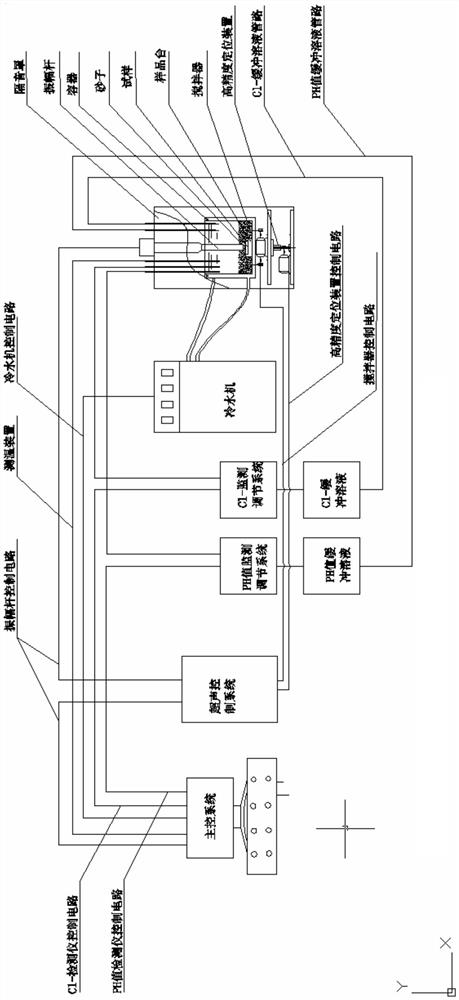
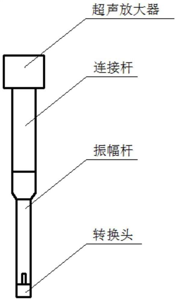
The invention discloses a device and a method suitable for detecting cavitation resistance of a surface material of a flow passage component of hydraulic machinery. The device comprises a sound insulation cover, a lifting device, a container, an ultrasonic generator and a control system, wherein the ultrasonic generator is mounted on the sound insulation cover and comprises an ultrasonic amplifier, a connecting rod, an amplitude rod and a conversion head which are connected in sequence, and the whole device can be used for detecting the cavitation performance of a surface material, especially a thermal spraying coating, under different pH values, Cl<-> contents, temperatures, water flow rates, sand granularity and contents, cavitation power, frequencies and time; the cavitation performance detection conditions can be greatly enriched, and the actual situation can be better simulated. The whole scheme has no limitation on the material of the test sample, and the application range is wide; by using the method, whether the prepared coating meets the use requirements of a product or not can be mastered in time, and thermal spraying process adjustment is guided to meet requirements of the product.

Description

technical field [0001] The invention relates to the technical field of surface strengthening and remanufacturing coating detection, in particular to a device and method suitable for detecting cavitation performance of surface materials of hydraulic machinery flow parts, which can be used for detection of cavitation performance of thermal spray coatings. Background technique [0002] Cavitation is one of the common failure modes of hydraulic turbines, water pumps, ship propellers and other equipment and their parts. Cavitation will cause erosion of mechanical equipment and parts, resulting in a decline in the overall performance of the equipment, generating noise, reducing the service life of the equipment and causing damage to the equipment. Safe operation brings hidden dangers and causes a lot of economic losses every year. [0003] At present, researchers mainly use new material development and new process research to improve the anti-cavitation performance of the equipmen...

Claims


Application Information

Patent Timeline
Patent Type & Authority Applications(China)
IPC IPC(8): G01N17/00G01N15/08G01B11/24G01N23/2251
CPCG01N17/00G01N15/088G01B11/24G01N23/2251
Inventor 陈小明伏利毛鹏展方勇惠希东赵坚刘伟张凯张磊霍嘉翔苏建灏曹文菁
Owner MIN OF WATER RESOURCES HANGZHOU MACHINERY DESIGN INST
Why Eureka
Try Eureka