Preparation method of direct type backlight lens

A direct type and lens technology, which is applied in the field of direct type backlight lens preparation, can solve the problems of low light energy utilization rate of backlight lens, low energy utilization rate of LED chips, and affecting light distribution brightness, etc., to achieve sufficient and uniform illumination brightness , improve brightness, improve the effect of integration

Active Publication Date: 2021-12-21
YEJIA OPTICAL TECH GUANGDONG CORP
View PDF8 Cites 0 Cited by
  • Summary
  • Abstract
  • Description
  • Claims
  • Application Information

AI Technical Summary

Problems solved by technology

[0003]In the prior art, the backlight lens is usually set as a plano-convex mirror structure, and an inwardly recessed light cavity structure is set on the plane of the lens, and the light source is placed on the When placed in the optical cavity, the light diverges around when passing through the inner wall of the optical cavity and enters the interior of the backlight lens, and finally refracts at the curved surface of the backlight lens to obtain a relatively uniform luminous effect. However, the backlight lens produced The utilization rate of light energy is not high, and the light path structure during work is as shown in Figure 1 As shown in , part of the light will be emitted from the larger angle formed between the surrounding edge and the optical axis, especially for miniature electronic products, this kind of edge divergence will seriously affect the brightness of the final light distribution , the LED chips that can be installed in miniature electronic products are relatively limited. The low energy utilization rate of a single LED chip will seriously affect the overall luminous brightness after forming a backlight module.

Method used


Image

  • Preparation method of direct type backlight lens
  • Preparation method of direct type backlight lens

Examples


Embodiment Construction

[0024] In order to further understand the features, technical means, and specific objectives and functions achieved by the present invention, the present invention will be further described in detail below in conjunction with the accompanying drawings and specific embodiments.

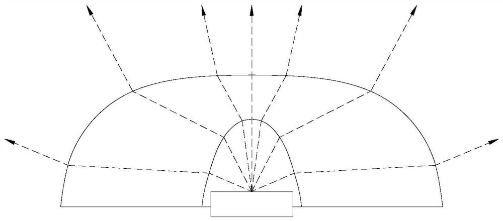
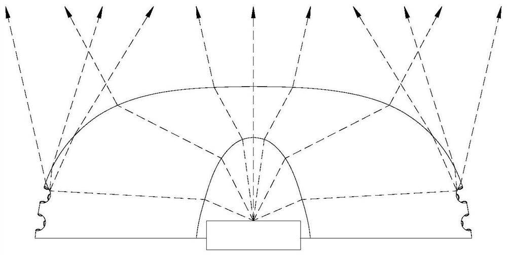
[0025] refer to figure 2 .

[0026] The embodiment of the present invention discloses a method for preparing a direct-type backlight lens, which includes the following steps in sequence:

[0027] S1. The lens body is made by injection molding. The two sides of the lens body are the installation plane and the light-emitting curved surface respectively, and an inwardly recessed optical cavity is formed at the center of the installation plane;

[0028] S2. Cover each surface of the lens body with a positive photoresist to obtain a protective mask layer, and the protective mask layer covers the installation plane, the light-emitting curved surface, and the inner wall of the optical cavity;

[0029] S3. ...


PUM


Abstract

The invention provides a preparation method of a direct type backlight lens. The preparation method comprises the following steps: injection molding: the two sides of the lens body are respectively provided with a mounting plane and a light emitting curved surface, and the center of the mounting plane is provided with a light accommodating cavity; the lens body is coated with positive photoresist to obtain a mask protection layer; dimming hole grooves are carved on the light emitting curved surface of the lens body by laser, an included angle alpha is formed between the connecting line of the dimming hole grooves and a light containing groove and the optical axis of the light containing cavity, and alpha is larger than or equal to 60 degrees and smaller than 90 degrees; metal materials are sputtered on the dimming hole grooves through magnetron sputtering, and metal matrixes are formed on the inner walls of the dimming hole grooves; the surfaces of the metal matrixes react with a reflecting salt solution to form a reflecting layer; and a mask protection layer is removed by using a UV lamp. A plurality of dimming hole grooves are formed in the edge area of the light emitting curved surface, the metal substrates and the reflecting layers are formed in the dimming hole grooves, incoming light can be reflected and refracted for multiple times, and the brightness is sufficient; the dimming hole grooves obtained through laser processing are used as basic positioning, and high-precision processing can be formed.

Description

technical field [0001] The invention relates to a backlight lens, and specifically discloses a preparation method of a direct-type backlight lens. Background technique [0002] Backlight lens is also called diffusion lens and TV lens. A backlight lens is usually equipped with an LED chip, which can form a uniform and divergent lighting effect. It is mostly used in direct lighting modules. For surface glow lighting. [0003] In the prior art, the backlight lens is usually set as a plano-convex mirror structure, and an inwardly recessed optical cavity structure is arranged on the plane of the lens. The light source is placed in the optical cavity, and the light passes through the inner wall of the optical cavity. It diverges and enters the interior of the backlight lens, and finally emits after refraction at the curved surface of the backlight lens to obtain a relatively uniform luminous effect, but the light energy utilization rate of the prepared backlight lens is not high,...

Claims


Application Information

Patent Timeline
Patent Type & Authority Applications(China)
IPC IPC(8): G02B3/00G02F1/13357
CPCG02B3/00G02F1/133607G02F1/133605
Inventor 南基学
Owner YEJIA OPTICAL TECH GUANGDONG CORP
Why Eureka
Try Eureka