
An intumescent coating for steel structures

An expansion type, steel structure technology, applied in fireproof coatings, epoxy resin coatings, coatings, etc., can solve problems such as loss of cohesion of the charcoal layer, loss of steel structure protection, cracking of the charcoal layer, etc., to achieve stability of the steel structure The effect of reducing resistance, avoiding cracking, and enhancing flame retardancy

Active Publication Date: 2022-05-17
应急管理部四川消防研究所
View PDF0 Cites 0 Cited by
  • Summary
  • Abstract
  • Description
  • Claims
  • Application Information

AI Technical Summary

Problems solved by technology

[0004] However, in the actual process, as the combustion temperature increases, the coke layer formed will lose its cohesion at high temperature, which will cause the coke layer to crack and lose the protection of the steel structure.

Method used


Image

  • An intumescent coating for steel structures
  • An intumescent coating for steel structures
  • An intumescent coating for steel structures

Examples


preparation example Construction

[0025] 1. Preparation of borosilicate resin:

[0026] The preparation method of borosilicate resin among the present invention comprises the following steps:

[0027] Step 1, phenyltriethoxysilane and dimethyldiethoxysilane are mixed in a mass molar ratio of 1:1 to obtain a mixed silane monomer, and then the mixed silane monomer and boric acid are mixed in a mass molar ratio of 2:1 was mixed to obtain mixture 1.

[0028] Step 2. On the basis of step 1, add 100ml of absolute ethanol to mixture 1 for mixing, and then add hydrochloric acid and deionized water with a molar concentration of 1mol / L on the basis of mixing mixture 1 and absolute ethanol , and finally hydrolyzed at 60°C for 3h. Wherein, the volume of hydrochloric acid is 5% of the volume of the mixed silane monomer, and the deionized water is 60% of the water required for the complete hydrolysis of the mixed silane monomer.

[0029] Step 3. On the basis of step 2, continue to heat up to 130° C., polycondense for 2 h...

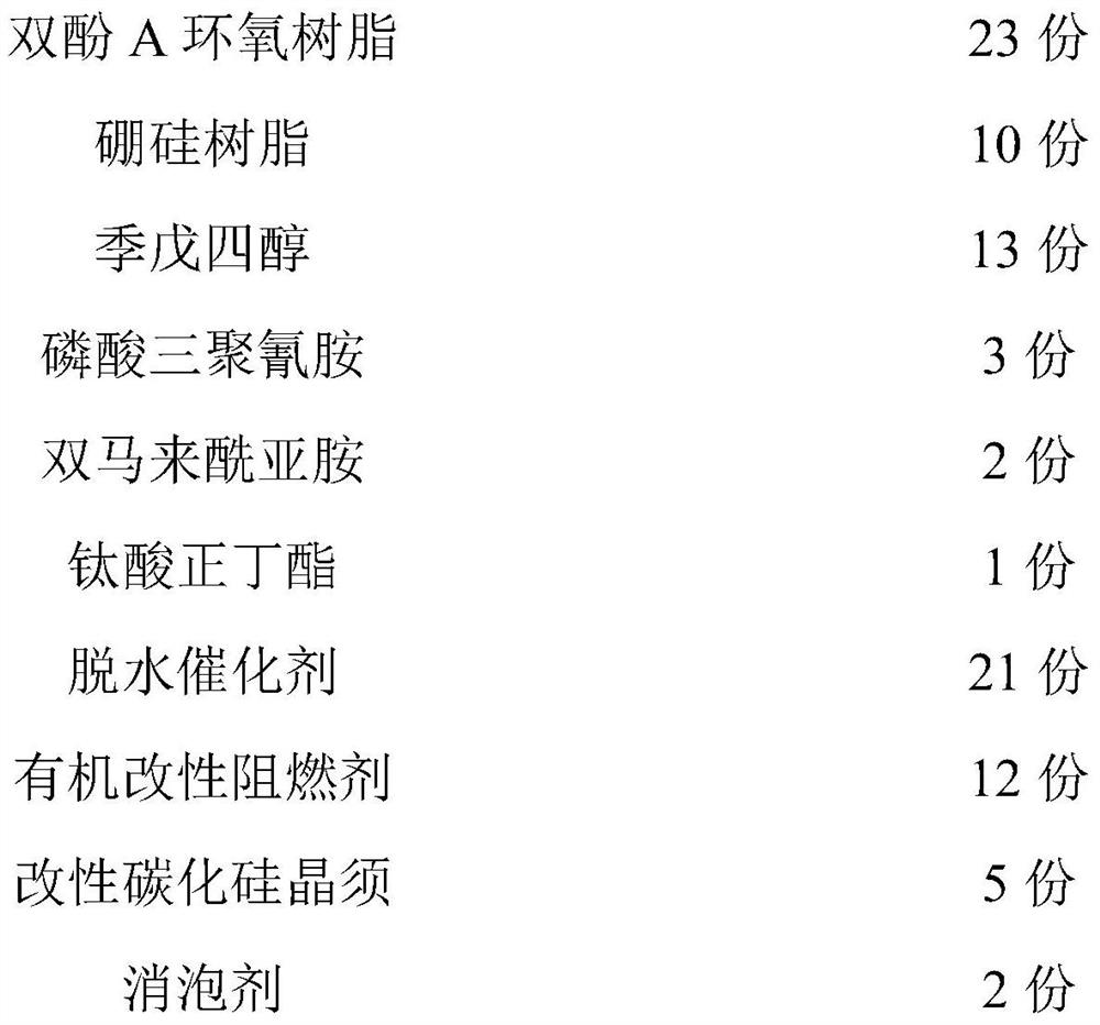
Embodiment 1

[0044] A kind of intumescent paint for steel structure, by weight, comprises following component:

[0045]

[0046] Wherein, the dehydration catalyst in this embodiment is composed of amidinourea phosphate, ammonium polyphosphate and melamine pyrophosphate; wherein, the mass ratio of amidinourea phosphate, ammonium polyphosphate and melamine pyrophosphate is 2:1:1.

[0047] The antifoaming agent in this embodiment selects simethicone oil.

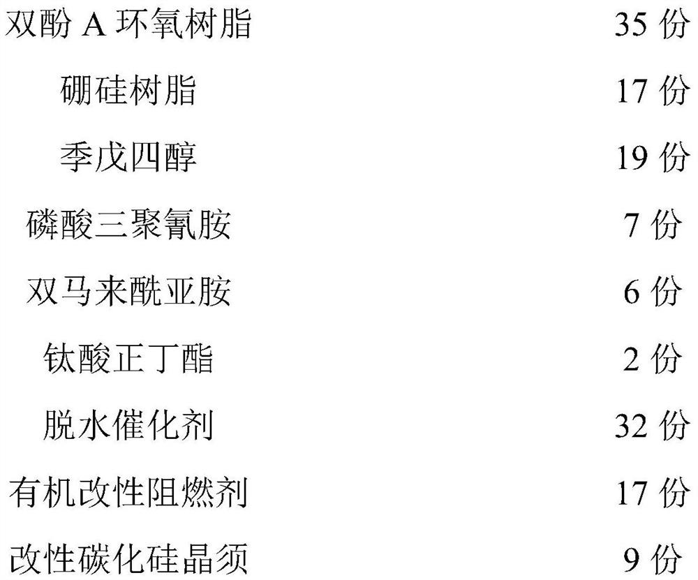
Embodiment 2

[0049] A kind of intumescent paint for steel structure, by weight, comprises following component:

[0050]

[0051]

[0052] Wherein, the dehydration catalyst in this embodiment is composed of amidinourea phosphate, ammonium polyphosphate and melamine pyrophosphate; wherein, the mass ratio of amidinourea phosphate, ammonium polyphosphate and melamine pyrophosphate is 2:1:1.

[0053] The antifoaming agent in this embodiment selects simethicone oil.


PUM


Abstract

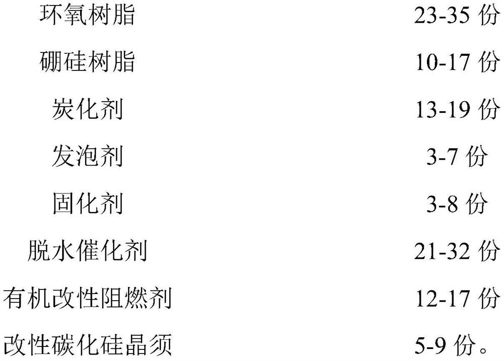
The invention discloses an intumescent coating for steel structures. The intumescent coating in the invention includes epoxy resin, borosilicate resin, carbonizing agent, foaming agent, curing agent, dehydration catalyst, organically modified flame retardant, Modified silicon carbide whiskers. Among them, the organic modified flame retardant is phosphorus nitrogen compound modified LDHs. In the present invention, during the heating process, the crystallization water in the LDHs in the organically modified flame retardant in the coating and the hydroxyl group on the laminate will absorb a large amount of heat during thermal decomposition (below 200 ° C), and simultaneously release The large amount of water vapor, therefore, lowers the temperature of the intumescent coating and simultaneously lowers the concentration of flammable gases and oxidizers. As the combustion proceeds, part of the organic modified flame retardant moves to the outside of the foamed carbon layer with the formation of the foamed carbon layer of the foaming agent. The organic modified flame retardant is formed at high temperature by magnesium oxide and aluminum oxide The composed metal oxide layer can insulate heat transfer to the carbon foam layer, thereby realizing the protection of the internal steel structure.

Description

technical field [0001] The invention relates to the field of coatings, in particular to an expansion coating for steel structures. Background technique [0002] With the continuous improvement and development of construction technology, various types of buildings have emerged as the times require. As the dominant structural material in buildings, steel is widely used in high-rise, long-span and complex structures due to its high strength, good ductility, light weight, good plasticity and toughness, especially in the Skyscrapers stadiums, opera houses, etc. around the world. However, with the gradual deepening of people's research on steel, the disadvantages of steel structures under fire conditions are becoming more and more obvious. At high temperatures, the yield strength, tensile strength, and elastic modulus of the steel structure decrease, and the strength and stiffness deteriorate rapidly. Especially at 450°C to 650°C, the steel column will bend, resulting in large d...

Claims


Application Information

Patent Timeline
Patent Type & Authority Patents(China)
IPC IPC(8): C09D163/00C09D163/04C09D183/08C09D5/18C09D7/62
CPCC09D163/00C09D5/185C09D7/62C09D7/70C08L2201/08C08L2201/02C08L83/04C08L63/04C08K9/04C08K9/06C08K7/00C08K3/26C08K5/5455C08K7/10C08K5/053C08K13/06
Inventor 何世家唐胜利张泽江葛欣国钟波黄浩张天昊曹怡孟志张正卿张帆金素艳王屹韬
Owner 应急管理部四川消防研究所
Learn More