
Full-automatic taking and placing grinding device for optical lens machining

A technology for optical lenses and grinding devices, applied in grinding/polishing safety devices, grinding drive devices, metal processing equipment, etc., can solve the problem of troublesome manual lens picking and placing

Active Publication Date: 2021-05-11
聚科光电科技(武汉)有限公司
View PDF7 Cites 3 Cited by
  • Summary
  • Abstract
  • Description
  • Claims
  • Application Information

AI Technical Summary

Problems solved by technology

[0003] When processing optical lenses, it is often necessary to polish the lens, place the lens on the placement table, and then grind it with a grinding roller. When the traditional lens is polished, the staff needs to place the lens on the placement table. It is also necessary for the staff to take out the lens. In order to prevent debris from flying around, the lens is often polished in a closed space, so it is very troublesome for the staff to manually pick and place the lens. Therefore, we need to design an optical lens. Fully automatic pick-and-place grinding device to solve the above problems

Method used


Image

  • Full-automatic taking and placing grinding device for optical lens machining
  • Full-automatic taking and placing grinding device for optical lens machining
  • Full-automatic taking and placing grinding device for optical lens machining

Examples


Embodiment 1

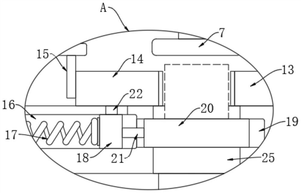
[0024] refer to Figure 1-3 , a fully automatic pick-and-place grinding device for optical lens processing, including a housing 1, and a switchable sliding door (not shown) can be installed on the front side of the housing 1 to facilitate the removal of the lens. There is a grinding chamber 2, which is provided with a device plate 4 for sliding up and down. The inner walls of both sides of the grinding chamber 2 are provided with guide grooves, and two guide grooves are provided with sliding guide blocks. The two guide blocks are respectively It is fixedly connected with both sides of the device plate 4, and the movement of the device plate 4 is started to guide. Two electric telescopic rods 5 are installed on the inner bottom of the grinding chamber 2, and the telescopic ends of the two electric telescopic rods 5 are connected to the ends of the device plate 4. The lower end is fixedly connected, and the telescopic expansion of the two electric telescopic rods 5 drives the de...

Embodiment 2

[0032] refer to Figure 4-5 , The difference between this embodiment and Embodiment 1 is that the inner bottom of the grinding chamber 2 is provided with a reciprocating screw rod 26 for rotation, and the reciprocating screw rod 26 and the rotating rod 6 are equipped with transmission wheels 27. Wheel 27 is connected by drive belt 28 transmission, and the rotation of rotating rod 6 is driven the rotation of reciprocating screw mandrel 26 by the transmission of drive wheel 27 and drive belt 28, and the upper end of housing 1 is equipped with water tank 35, offers water inlet on the water tank 35, facilitates Water is added, and the inner top of the grinding chamber 2 is fixedly connected with two fixed rods 29, and the lower ends of the two fixed rods 29 are fixedly connected with a fixed plate 30. The rods 26 are threaded, and the two fixed rods 29 guide the movement of the threaded block. An air bag 31 is installed between the lower end of the threaded block and the upper end...


PUM


Abstract

The invention discloses a full-automatic taking and placing grinding device for optical lens machining. The full-automatic taking and placing grinding device comprises a shell and a containing mechanism, a grinding chamber is formed in the shell, a device plate used for sliding up and down is arranged in the grinding chamber, and two electric telescopic rods are installed at the inner bottom of the grinding chamber; the telescopic ends of the two electric telescopic rods are fixedly connected with the lower end of the device plate; and the containing mechanism comprises a containing cylinder fixedly connected to the top in the grinding chamber, the upper end of the containing cylinder penetrates through the shell and communicates with the outside, and two supporting frames are fixedly connected to the upper end of the device plate. When the device is used, the device plate is driven by the two electric telescopic rods to move up and down, lenses can be automatically taken and placed when the device plate moves up and down, workers do not need to manually take and place the lenses, meanwhile, water can be sprayed on grinding rollers when rotating rods rotate, and the situation that chippings fly around is reduced.

Description

technical field [0001] The invention relates to the field of optical lens processing, in particular to a fully automatic pick-and-place grinding device for optical lens processing. Background technique [0002] Optical lens is optical glass. Optical glass is mixed with high-purity silicon, boron, sodium, potassium, zinc, lead, magnesium, calcium, barium and other oxides according to a specific formula, melted in a platinum crucible at high temperature, and stirred evenly with ultrasonic waves. , to remove air bubbles, and then cool down slowly for a long time to avoid internal stress in the glass block. The cooled glass block must be measured by optical instruments to check whether the purity, transparency, uniformity, refractive index and dispersion rate meet the specifications. The glass block is heated and forged to form an optical lens blank. [0003] When processing optical lenses, it is often necessary to polish the lens, place the lens on the placement table, and the...

Claims


Application Information

Patent Timeline
IPC IPC(8): B24B19/00B24B41/04B24B41/06B24B47/12B24B47/20B24B47/22B24B55/03
CPCB24B19/00B24B41/06B24B47/22B24B41/04B24B47/12B24B47/20B24B55/03
Inventor 阙建波
Owner 聚科光电科技(武汉)有限公司
Learn More