
A kind of dielectric ceramic, multilayer ceramic capacitor

A dielectric and ceramic technology, applied in the field of multilayer ceramic capacitors, can solve the problems of inability to improve product thermal shock resistance, undefined secondary phase size, poor thermal shock resistance, etc., to improve thermal shock resistance and improve bonding Force, the effect of improving thermal shock resistance

Active Publication Date: 2021-11-05
CHAOZHOU THREE CIRCLE GRP +1
View PDF2 Cites 0 Cited by
  • Summary
  • Abstract
  • Description
  • Claims
  • Application Information

AI Technical Summary

Problems solved by technology

However, this dielectric ceramic is mainly composed of perovskite compounds represented by ABO3, and there is a second phase such as R-Ni-Ti, which has poor thermal shock resistance. In the 1μm dielectric ceramic layer, it is easier to generate cracks under thermal shock conditions
The dielectric ceramics disclosed in CN102372484B are mainly composed of perovskite compounds represented by ABO, and crystalline oxides containing Al, Mg and Si exist as secondary phase particles, which do not damage the dielectric properties, insulation, temperature characteristics, high temperature load characteristics and other properties, it has good thermal shock resistance, but the mechanism is not explained, and the size of the secondary phase is not defined in this patent. According to our experimental results, when the secondary phase The size of the product reaches a certain level and cannot improve the thermal shock resistance of the product

Method used


Image

  • A kind of dielectric ceramic, multilayer ceramic capacitor
  • A kind of dielectric ceramic, multilayer ceramic capacitor
  • A kind of dielectric ceramic, multilayer ceramic capacitor

Examples


preparation example Construction

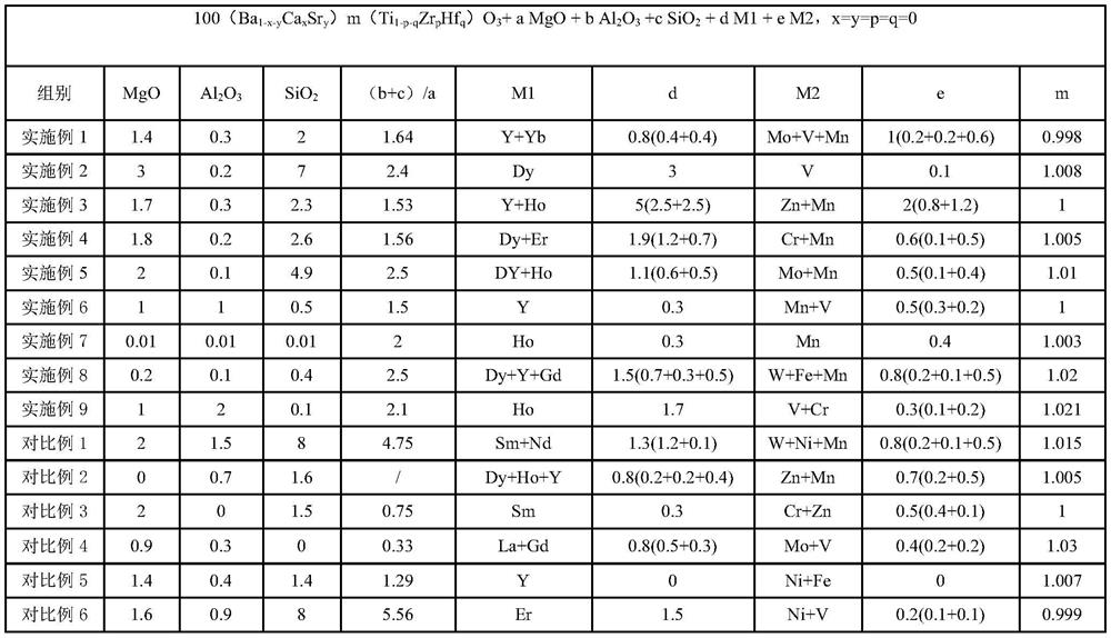
[0034] The preparation method of the multilayer ceramic capacitor of embodiment 1-9 and comparative example 1-8 comprises the following steps:

[0035] (1) Prepare Ba compound and Ti compound, prepare Ca compound, Sr compound, Zr compound and Hf compound according to actual needs, prepare barium titanate compound powder with an average particle size of 0.1-0.3 μm as the main component, barium titanate The compound powder can be prepared by solid phase method, co-precipitation method, hydrothermal method, oxalate method and other methods;

[0036] (2) According to the composition of Table 1, prepare minor components such as rare earth compounds, transition metal compounds, and Si compounds, and weigh according to a predetermined ratio; then these weighing objects are mixed with BaTiO 3 The powder, pulverization medium and pure water are put into the ball mill together, fully mixed and pulverized in a wet way, mixed, and dried to obtain ceramic raw material powder;

[0037] (3)...

Embodiment 4

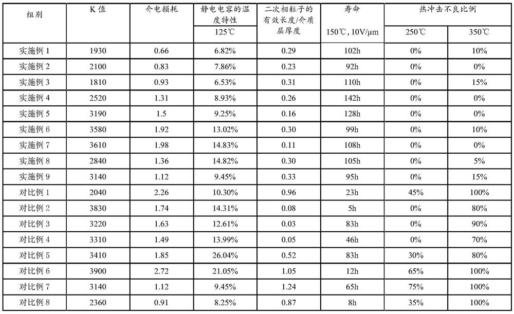
[0060] Example 4 has relatively moderate (b+c) / a value, m value, and its secondary phase length also conforms to 1 / 10<the effective length of the long rod-shaped secondary phase particles / the thickness of the dielectric layer of the multilayer ceramic capacitor< The requirement of 1 / 3 improves the thermal shock resistance of the product while ensuring the product life characteristics.


PUM

PropertyMeasurementUnit
thicknessaaaaaaaaaa

Abstract

The invention discloses a dielectric ceramic and multilayer ceramic capacitor. There are secondary phase particles containing Al, Mg and Si in the dielectric ceramic of the present invention. By making the secondary phase particles form a long rod-shaped structure, the long rod-shaped secondary phase particles play a certain anchoring effect on the dielectric layer and internal electrodes, Improved interfacial bonding, resulting in improved thermal shock resistance. Moreover, the present invention controls the size of the Mg-Al-Si secondary phase particles by optimizing the composition of the dielectric ceramics, thereby ensuring that the long rod-shaped secondary phase particles can improve the thermal shock resistance of the product while avoiding secondary phase particles. The problem of life-span deterioration caused by excessively large secondary phases enables the further thinning and multi-layering of the dielectric layer of multilayer ceramic capacitors to meet the market demand for small size and large capacity.

Description

technical field [0001] The present invention relates to a dielectric ceramic and a multilayer ceramic capacitor using it, in particular to a dielectric ceramic that improves the bonding force and reliability of the ceramic structure through optimization of the crystal structure of the material, and a multilayer ceramic manufactured using the dielectric ceramic capacitor. Background technique [0002] With the development of the electronic information industry, more and more electronic components are made of ceramic materials, such as capacitors, piezoelectric devices, varistors, and thermistors. Multilayer ceramic capacitors, as one of the representative ceramic electronic components, usually consist of a ceramic body (composed of ceramic materials), internal electrodes (located inside the ceramic body to form a multilayer structure) and external electrodes (located outside the ceramic body to connect The corresponding internal electrode) is composed of three parts. At pres...

Claims


Application Information

Patent Timeline
Patent Type & Authority Patents(China)
IPC IPC(8): C04B35/468C04B35/49C04B35/80H01G4/30H01G4/12
CPCC04B35/4682C04B35/49C04B2235/3206C04B2235/3208C04B2235/3213C04B2235/3217C04B2235/3418C04B2235/40C04B2235/404C04B2235/405H01G4/1227H01G4/30
Inventor 马艳红邱基华孙健
Owner CHAOZHOU THREE CIRCLE GRP
Learn More