Optical lens processing device

A technology for processing devices and optical lenses, which is applied in the direction of grinding/polishing safety devices, grinding drive devices, metal processing equipment, etc., can solve the problems of uneven grinding effect of the edge of the lens, low processing efficiency, waste of resources, etc., to achieve Reduce the labor load of personnel, improve work efficiency, and achieve uniform grinding effect

Pending Publication Date: 2021-03-16
彭广荣
View PDF0 Cites 1 Cited by
  • Summary
  • Abstract
  • Description
  • Claims
  • Application Information

AI Technical Summary

Problems solved by technology

[0003] During the processing of optical lenses, it is necessary to grind the edges and corners of the lens. The clamping range of the optical lens is limited in the prior art, and it cannot adapt to the size and shape of different optical lenses. The stability is poor and the processing efficiency is low. In addition, in the process of grinding Among them, the grinding effect of the edge of the lens is uneven and too monotonous, and the grinding wheel is continuously rotating, which causes excessive energy consumption and wastes resources. Therefore, in view of this, research and improvement are made on the existing structure and defects to provide optical lens processing device, in order to achieve a more practical purpose

Method used


Image

  • Optical lens processing device
  • Optical lens processing device
  • Optical lens processing device

Examples


Embodiment Construction

[0022] The present invention will be further described below in conjunction with accompanying drawing:

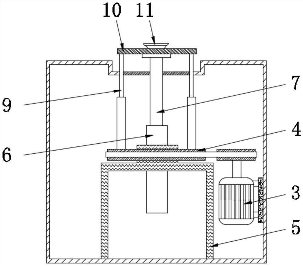
[0023] The invention provides an optical lens processing device, such as the attached figure 1 To attach Figure 5 Shown: including machine base 1, workbench 2 is fixedly installed on the upper surface of machine base 1, and drive motor 3 is fixedly installed on the inner wall of machine base 1, and the output end of drive motor 3 is fixedly connected with pulley 4, and pulley 4 is installed in rotation Outside the bearing seat 5, a sleeve 6 runs through the inner center of the bearing seat 5. A support rod 7 is slidably installed inside the sleeve 6. A coil 602 is arranged at the bottom end of the support rod 7. Below the coil 602 and on the sleeve Corresponding coils 602 are arranged inside the tube 6, and the connection between the support rod 7 and the sleeve 6 is fixedly installed with a limit block 8 on the inner wall of the sleeve 6, and a telescopic rod 9 is fixedl...


PUM


Abstract

The invention provides an optical lens processing device, which is characterized in that fixed blocks are fixedly mounted on the upper surface of a workbench; movable rods are movably mounted on the inner sides of the adjacent fixed blocks; rollers are rotatably mounted at the tail ends of the movable rods, and compression springs are fixedly connected to the upper surfaces of the adjacent rollers; and the rollers are arranged on the left and right side surfaces of a moving seat. In the process that a sliding plate pushes a mounting base, the rollers roll inwards at the same time through a compression spring and the inclined face of the moving seat to drive the movable rods to be folded inwards till the movable rods and a grinding wheel at the top end of the moving seat coincide and are tightly attached to the edge of an optical lens, and clamping and loosening of the optical lenses of different sizes and shapes are achieved; and during grinding, fan blades are driven to rotate throughrotation of the grinding wheel, generated powder is introduced into a hollow bearing and conveyed into a collecting box through a hose, the uniform grinding effect of the optical lens is guaranteed,meanwhile, the personnel cleaning amount is reduced, and the surface of the optical lens is prevented from being polluted greatly.

Description

technical field [0001] The invention belongs to the technical field of optical processing equipment, and in particular relates to an optical lens processing device. Background technique [0002] The optical lens is mixed with high-purity silicon, boron, sodium, potassium, zinc, lead, magnesium, calcium, barium and other oxides according to a specific formula, melted in a platinum crucible at high temperature, stirred evenly with ultrasonic waves, and removed bubbles, and then subjected to long-term The optical lens is made by slowly cooling down over time. The optical lens is an indispensable part of the machine vision system. It is an important part of imaging through the refraction of light. It requires high precision. on the device. [0003] During the processing of optical lenses, it is necessary to grind the edges and corners of the lens. The clamping range of the optical lens is limited in the prior art, and it cannot adapt to the size and shape of different optical l...

Claims


Application Information

Patent Timeline
Patent Type & Authority Applications(China)
IPC IPC(8): B24B9/14B24B47/12B24B41/06B24B55/06B24B47/22
CPCB24B9/14B24B9/146B24B41/06B24B47/12B24B47/225B24B55/06
Inventor 彭广荣
Owner 彭广荣
Why Eureka
Try Eureka