
Heat pipe with axial and lateral flexibility

a heat pipe and flexible technology, applied in the field of flexible heat pipes, can solve the problem of small bellows that may be required

Inactive Publication Date: 2006-04-27
THERMAL
View PDF5 Cites 49 Cited by
  • Summary
  • Abstract
  • Description
  • Claims
  • Application Information

AI Technical Summary

Benefits of technology

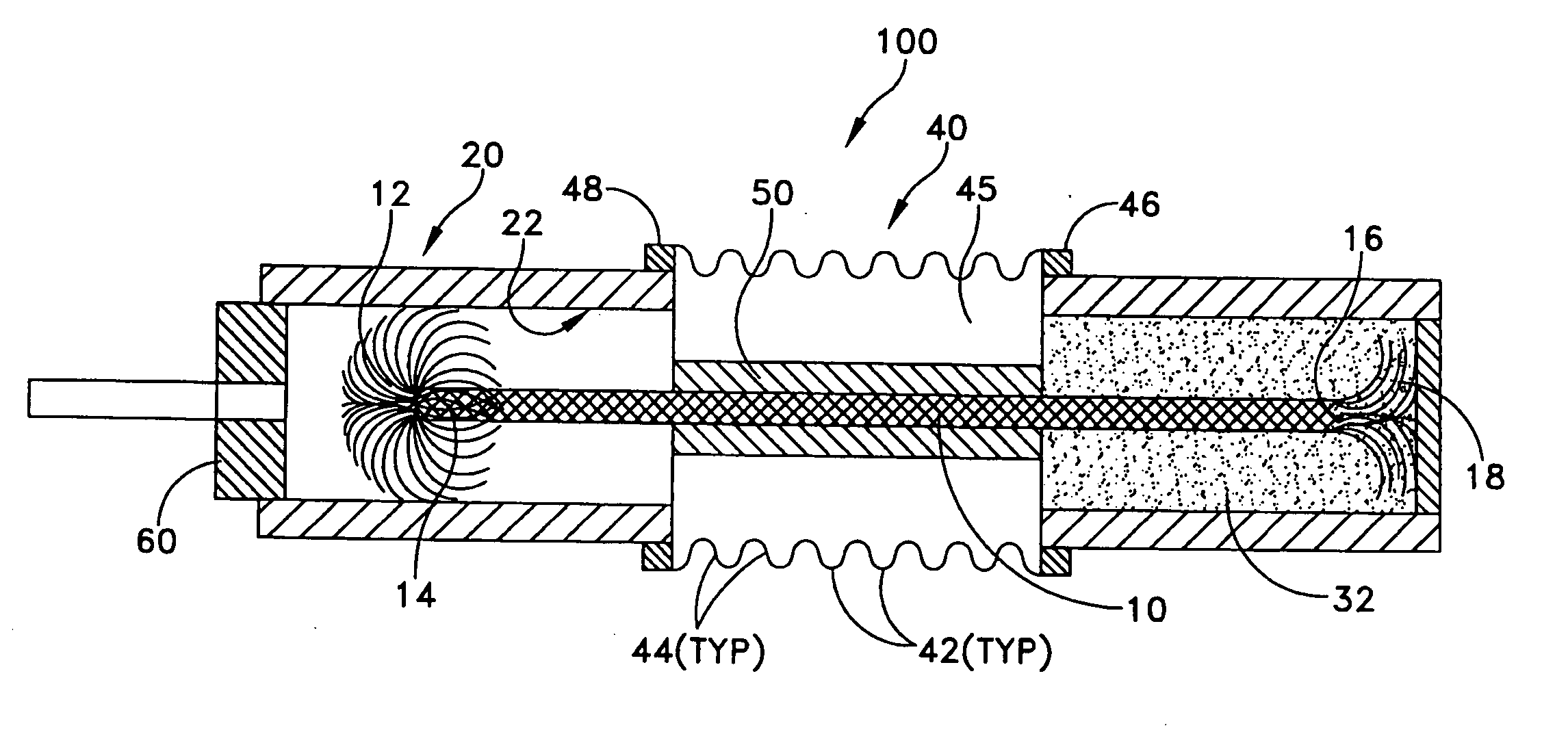
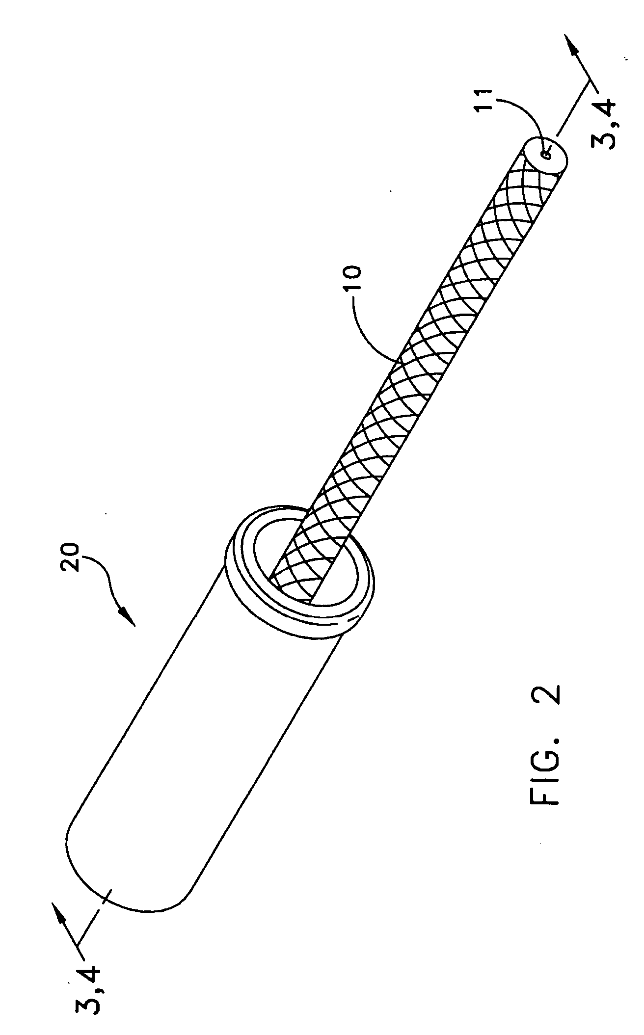
[0011] In one embodiment the heat pipe comprises a cable artery having a sliding connection to the condenser that provides freedom of movement between the condenser and the heat pipe (and the evaporator), in both the axial as well as lateral directions. A polytetrafluoroethylene (PTFE or Teflon®) sleeve can be provided over the cable artery to protect the bellows from abrasion due to contact with the cable artery.
[0013] A bellows may be used to provide flexibility in the heat pipe envelope. Due to the small size of the overall envelope associated with modern electronic devices, a very small bellows may be required. Such a bellows may have a very thin wall, which in one embodiment may be less than 0.001-inch thick. To protect the bellows from abrasion damage from the cable artery during flexing, a PTFE sleeve may be used. The sleeve may be slid over the cable artery and fixed between cable and bellows. The sleeve may be perforated to allow vapor to escape, so that the cable artery wick can prime.
[0016] A flexible heat pipe assembly is additionally disclosed, comprising a metal cable artery having first and second ends, the first end being turned inside out and folded back over onto itself to form an increased-diameter portion. A condenser may be provided having an inner surface dimensioned to engage the increased-diameter portion of the cable artery. An evaporator may be connected to the second end of the tubular member; and a bellows member may surround the cable artery. The bellows may have a first end connected to the condenser and a second end connected to the evaporator. Thusly arranged, the engagement between the tubular member and the condenser may allow relative axial movement between the artery and condenser pieces during operation. Additionally, the cable artery may be laterally flexible to allow the condenser and evaporator to move laterally with respect to each other during operation. Further, the cable artery may be capable of transporting condensed working fluid from the condenser to the evaporator by capillary action.

Problems solved by technology

Due to the small size of the overall envelope associated with modern electronic devices, a very small bellows may be required.

Method used


Image

  • Heat pipe with axial and lateral flexibility
  • Heat pipe with axial and lateral flexibility
  • Heat pipe with axial and lateral flexibility

Examples


Embodiment Construction

[0023] This description of preferred embodiments is intended to be read in connection with the accompanying drawings, which are to be considered part of the entire written description of this invention. The drawing figures are not necessarily to scale and certain features of the invention may be shown exaggerated in scale or in somewhat schematic form in the interest of clarity and conciseness. In the description, relative terms such as “horizontal,”“vertical,”“up,”“down,”“top” and “bottom” as well as derivatives thereof (e.g., “horizontally,”“downwardly,”“upwardly,” etc.) should be construed to refer to the orientation as then described or as shown in the drawing figure under discussion. These relative terms are for convenience of description and normally are not intended to require a particular orientation. Terms including “inwardly” versus “outwardly,”“longitudinal” versus “lateral” and the like are to be interpreted relative to one another or relative to an axis of elongation, o...


PUM


Abstract

A flexible heat pipe is disclosed for use with evaporator and condenser elements for removing heat from electronic components. The flexible heat pipe comprises a bellows member fixed at one end to a condenser member and at an opposite end to an evaporator member. A cable artery is disposed within the bellows and is fixed at one end to the evaporator, and slidingly engages the condenser at the opposite end. The bellows acts as a flexible vapor envelope, and the cable artery acts as a flexible wick for directing condensed working fluid from the condenser back to the evaporator. The sliding connection between the cable artery and the condenser allows relative axial movement, and the inherent flexibility of the cable artery allows relative lateral movement. Thus, the condenser and evaporator can move in all directions with respect to each other, which can provide desired vibration isolation of the two components.

Description

CROSS-REFERENCE TO RELATED APPLICATION [0001] This is a non-provisional application of prior U.S. provisional patent application Ser. No. 60 / 621,748, filed Oct. 25, 2004, by J. Thayer et al., titled “Heat Pipe with Axial and Lateral Flexibility,” the entire contents of which application is incorporated by reference herein.FIELD OF THE INVENTION [0002] The present invention generally relates to heat pipes for removing heat from electrical components, and, more particularly, to a flexible heat pipe which allows axial and lateral movement between evaporator and condenser components engaged to opposite ends of the heat pipe. BACKGROUND OF THE INVENTION [0003] It has been suggested that a computer is a thermodynamic engine that sucks entropy out of data, turns that entropy into heat, and dumps the heat into the environment. The ability of prior art thermal management technology to get that waste heat out of semiconductor circuits and into the environment, at a reasonable cost, limits the...

Claims


Application Information

Patent Timeline
IPC IPC(8): F28D15/00
CPCF28D15/0241F28D15/046
Inventor THAYER, JOHN GILBERTSCHAEFFER, CLARK SCOTTAPICELLI, SAMUEL W.
Owner THERMAL
Learn More