
Surface acoustic wave filter packaging method and structure based on glass cover plate

A surface acoustic filter, glass cover technology, applied in electrical components, impedance networks, etc., can solve the problems of strict flatness requirements of substrates and sealing covers, filter damage, easy to change device performance, etc., to avoid the risk of splitting , the effect of improving reliability

Pending Publication Date: 2021-02-12
XIAMEN SKY SEMICON TECH CO LTD
View PDF6 Cites 4 Cited by
  • Summary
  • Abstract
  • Description
  • Claims
  • Application Information

AI Technical Summary

Problems solved by technology

[0005] 1. Substrate packaging is mainly carried out after scribing, which will pollute the IDT; if the IDT is passivated before scribing, the passivation layer will cover the surface of the IDT, which will increase the IDT mass load and make it easy to change the device Performance, while the passivation layer is too thin will cause IDT to not be able to form effective coverage;
[0006] 2. The reliability of the product has strict requirements on the flatness of the substrate and the sealing cover, which is easy to cause failure
[0007] 3. A series of uncertainties such as the accuracy of device installation, the influence of signal wires, and the angle of welding will cause inconsistency in device performance and even damage the filter
[0008] 4. The film-covered package on the surface of the device is sensitive to the size of the cavity, and it is easy to cause the film to collapse under a large cavity size, affecting the functional area of ​​the chip
[0009] 5. The film in the surface-covered package is made of organic materials, which will cause material outgassing at high temperatures, and organic matter will be deposited on the surface of the IDT functional area to cause chip contamination

Method used


Image

  • Surface acoustic wave filter packaging method and structure based on glass cover plate
  • Surface acoustic wave filter packaging method and structure based on glass cover plate
  • Surface acoustic wave filter packaging method and structure based on glass cover plate

Examples


Embodiment 2

[0061] see Figure 11 to Figure 12 , a surface acoustic filter packaging method and structure based on a glass cover, its main features are the same as in Embodiment 1, the difference is:

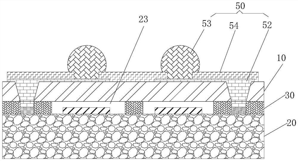
[0062] In step 5), making the metal connector 50 is specifically: by depositing a seed layer at the pad 21, electroplating and filling the through hole 12 of the glass cover 10 to form the metal connection circuit 51, and making the metal connection circuit 51 in the external connection area of ​​the metal connection circuit 51. The soldering portion 53 , the outer connection area of ​​the metal circuit is located directly above the pad 21 . That is, the metal line and the soldering portion 53 constitute the metal connector 50 .


PUM


Abstract

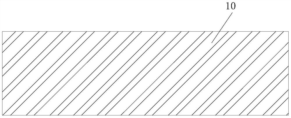
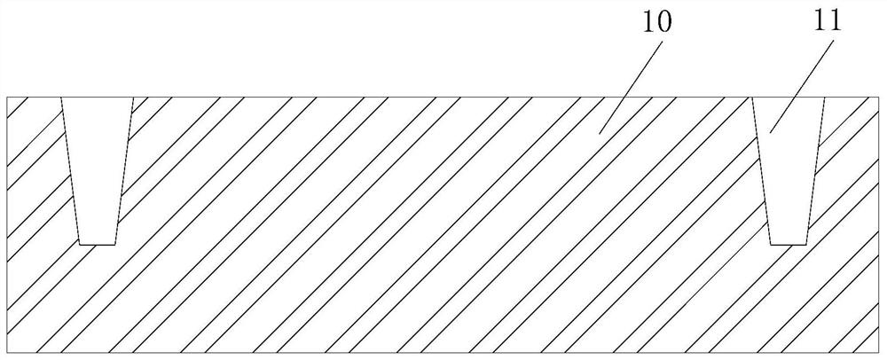
The invention discloses a surface acoustic wave filter packaging method and structure based on a glass cover plate, and the method comprises the steps: 1), providing the glass cover plate and a chip wafer, wherein a first surface of the chip wafer is provided with a bonding pad and an IDT functional region; (2) making a blind hole in the glass cover plate, temporarily bonding a glass carrier plateto the first surface of the opening side of the blind hole, grinding the other surface of the glass cover plate to get through the blind hole to form a through hole, wherein the inner diameter of thethrough hole is gradually decreased from the first surface to the other surface; (3) covering the first surface of the chip wafer with an insulating layer, and making openings in the positions, opposite to the bonding pad and the IDT functional region, of the insulating layer; 4) bonding the glass cover plate with the chip wafer, enabling the through hole to be opposite to the opening at the bonding pad of the insulating layer, and forming a cavity by the insulating layer and the glass cover plate in the IDT functional region; and 5) removing the glass carrier plate, and manufacturing a metalconnecting piece on the glass cover plate to be electrically connected with the bonding pad. The IDT functional region is prevented from being corroded by external moisture, corrosive liquid and thelike, the device packaging reliability is improved, one-time packaging is achieved, and batch production can be achieved.

Description

technical field [0001] The invention relates to the field of semiconductor packaging, in particular to a glass cover-based surface acoustic filter packaging method and structure. Background technique [0002] The surface acoustic filter uses an interdigital transducer (IDT) to excite, monitor and receive surface acoustic waves on piezoelectric materials such as lithium tantalate, lithium niobate, and quartz substrates, and completes the conversion and processing of electricity→acoustic→electricity. It integrates low insertion loss and good out-of-band suppression performance, can achieve wide bandwidth, small size, and filters RF signals in the RF front-end receiving channel. [0003] The mechanical structure of SAW filters is very fragile and easily damaged. In addition, the functional area of ​​the chip is very sensitive and cannot be in contact with any substance (such as dust, moisture, static electricity, etc.), otherwise it will affect the transmission of surface acou...

Claims


Application Information

Patent Timeline
Patent Type & Authority Applications(China)
IPC IPC(8): H03H9/64H03H9/02
CPCH03H9/64H03H9/02
Inventor 陈作桓于大全
Owner XIAMEN SKY SEMICON TECH CO LTD
Learn More