A Thin Wall Core Support Device for Square Pressure Parts Used in Cast Iron Alloy Forming

A technology of cast iron alloy and pressure parts, which is applied in the field of square pressure parts thin wall core support device, which can solve the problems of rising costs, poor fusion of molten iron, and difficulty in sand cores, etc.

Active Publication Date: 2021-04-16
TUPING MACHINERY JIANGSU CO LTD
View PDF10 Cites 0 Cited by
  • Summary
  • Abstract
  • Description
  • Claims
  • Application Information

AI Technical Summary

Problems solved by technology

In the prior art, the sand core of the square ingot mold in casting production is generally fixed by the core head, but sometimes the structure of the casting cannot make the core head in the required position, and the entire sand core is difficult to stabilize, so the core support is often used To strengthen the stability of the sand core, the core support in the existing process is generally made of low carbon steel. The melting point of this material is in the range of 1400 ° C ~ 1500 ° C, but the general pouring temperature of iron castings is in the range of 1350 ° C ~ 1400 ° C In general, there is no problem for castings with general requirements, but for castings under pressure, there will be a great risk of leakage. Therefore, a core support with a low melting point and a thin wall that is easy to fuse is required
When the core support of the square ingot mold is used to reinforce the sand core, the existing technology uses an integrated core support for reinforcement, and the integrated core support has many manufacturing processes, and a process error can easily make the entire core support At the same time, the core support is fixed by welding, and the reuse rate is low, which increases the cost, and the fusion of molten iron cannot be well realized during processing, and there are penetrative defects and the risk of leakage

Method used


Image

  • A Thin Wall Core Support Device for Square Pressure Parts Used in Cast Iron Alloy Forming
  • A Thin Wall Core Support Device for Square Pressure Parts Used in Cast Iron Alloy Forming
  • A Thin Wall Core Support Device for Square Pressure Parts Used in Cast Iron Alloy Forming

Examples


Embodiment Construction

[0031] The following will clearly and completely describe the technical solutions in the embodiments of the present invention with reference to the accompanying drawings in the embodiments of the present invention. Obviously, the described embodiments are only some of the embodiments of the present invention, not all of them. Based on the embodiments of the present invention, all other embodiments obtained by persons of ordinary skill in the art without making creative efforts belong to the protection scope of the present invention.

[0032] It should be noted that all directional indications (such as up, down, left, right, front, back...) in the embodiments of the present invention are only used to explain the relationship between the components in a certain posture (as shown in the figure). Relative positional relationship, movement conditions, etc., if the specific posture changes, the directional indication will also change accordingly.

[0033] In addition, in the present...


PUM


Abstract

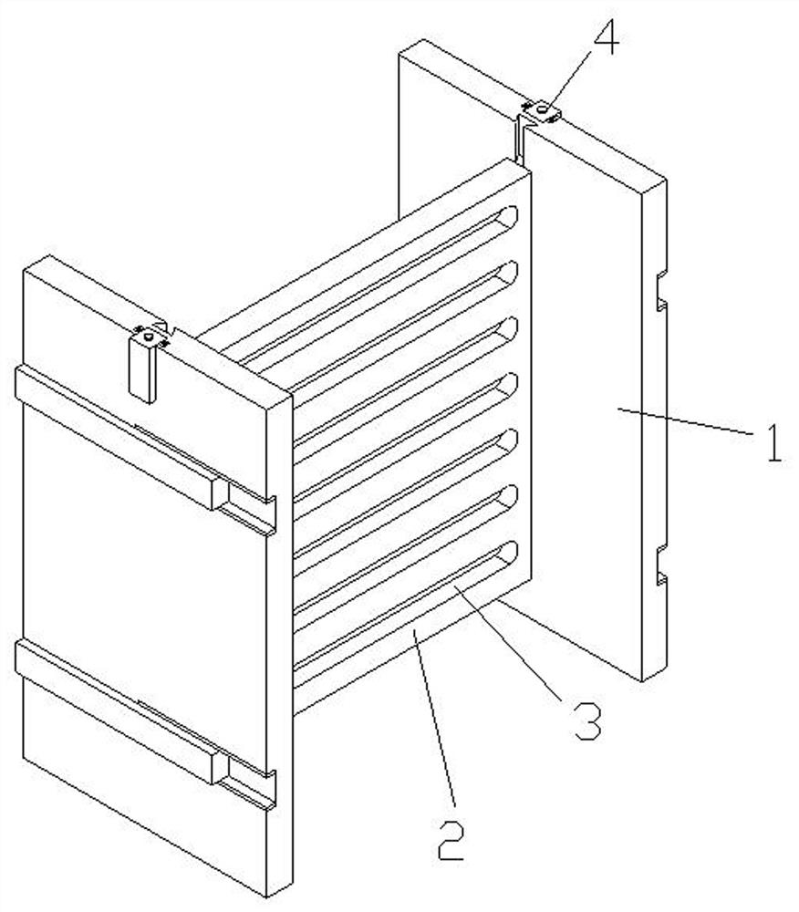
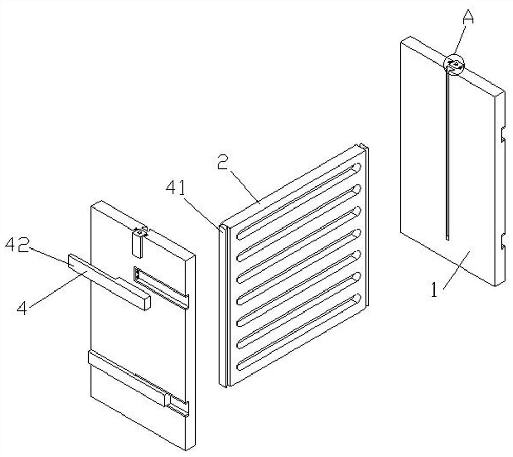
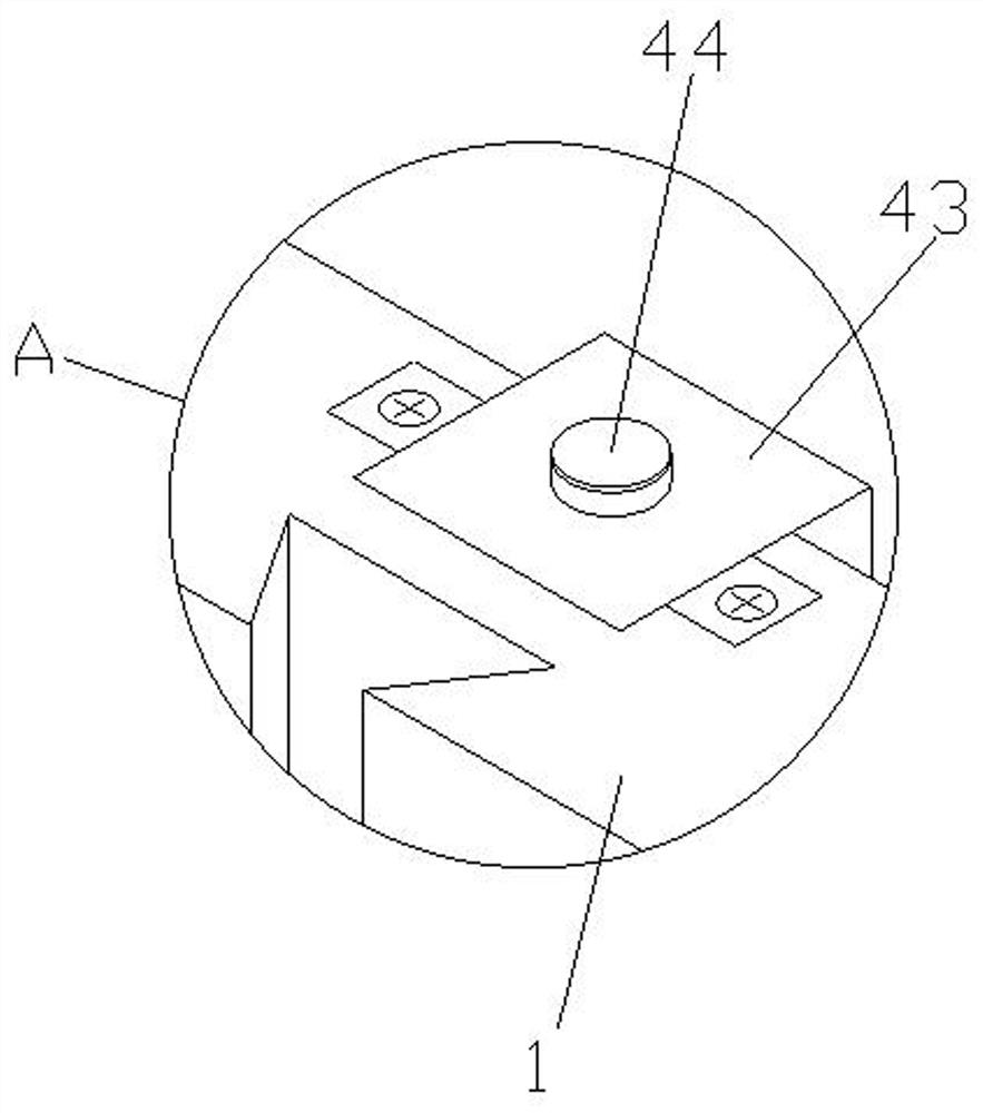
The invention relates to the technical field of core support devices, and discloses a thin wall core support device for square pressure pieces used for forming cast iron alloys. Including side plates, support plates, through-holes and positioning mechanisms, the present invention sets the positioning mechanism on the outside of the side plates and connects the core braces in a combined form. When one of the processing steps goes wrong, the corresponding parts can be directly replaced. At the same time, the support plate can be moved forward by pulling the side plate upwards to separate from the outer side of the welding plate and the connecting plate, so that most parts of the core support device can be quickly taken out for recycling, and the whole core support can be quickly disassembled and facilitated. Replacement, while facilitating repeated use, has the beneficial effect of reducing production costs. The side plate is made of cast iron, and is equipped with a galvanized layer at the same time, which can achieve better fusion between the molten iron and the core support. Threads are provided on the support plate, which can better fuse with the molten iron without causing penetration defects and minimize the risk of leakage.

Description

technical field [0001] The invention relates to the technical field of core support devices, in particular to a thin-wall core support device for square pressure pieces used for forming cast iron alloys. Background technique [0002] Alloy cast iron refers to cast iron with special properties by adding alloying elements to ordinary cast iron. The alloying elements usually added include silicon, manganese, phosphorus, nickel, chromium, molybdenum, copper, aluminum, boron, vanadium, titanium, antimony, tin, etc. , alloy cast iron is divided into low alloy cast iron (alloy element content < 3%) and medium alloy cast iron (alloy element content > 10%) according to the amount of alloy elements added. Alloy elements can change the matrix structure of cast iron, so that cast iron can obtain Special physical and chemical properties such as heat resistance, wear resistance, corrosion resistance, non-magnetic and low temperature resistance, so this cast iron is also called "spec...

Claims


Application Information

Patent Timeline
Patent Type & Authority Patents(China)
IPC IPC(8): B22C21/14C22C37/10
CPCB22C21/14C22C37/10
Inventor 薛陈忠张海锋
Owner TUPING MACHINERY JIANGSU CO LTD
Why Eureka
Try Eureka