
A kind of battery edge passivation method

An edge and battery technology, applied in circuits, electrical components, photovoltaic power generation, etc., can solve the problems of reducing the performance of small cells, increasing the loss of electrical performance, and damage to the edges of small cells, so as to improve photoelectric conversion efficiency, improve power generation performance, The effect of no pollution in the process

Active Publication Date: 2022-03-22
CHANGZHOU SHICHUANG ENERGY CO LTD
View PDF4 Cites 0 Cited by
  • Summary
  • Abstract
  • Description
  • Claims
  • Application Information

AI Technical Summary

Problems solved by technology

The cutting process is usually completed by laser cutting process, because the laser processing process will cause damage to the edge of the cut small cell, especially the doped junction (PN junction or high-low junction) or passivation contact structure (TOPCon) on the front and back of the cell. battery) is exposed and accompanied by the damage of this laser cutting process, and the edge surface of the small battery after cutting is not protected by any passivation layer, which will significantly reduce the performance of the small battery, thereby further increasing the Loss of electrical performance of their assembly into components

Method used


Image

  • A kind of battery edge passivation method

Examples


Embodiment 1

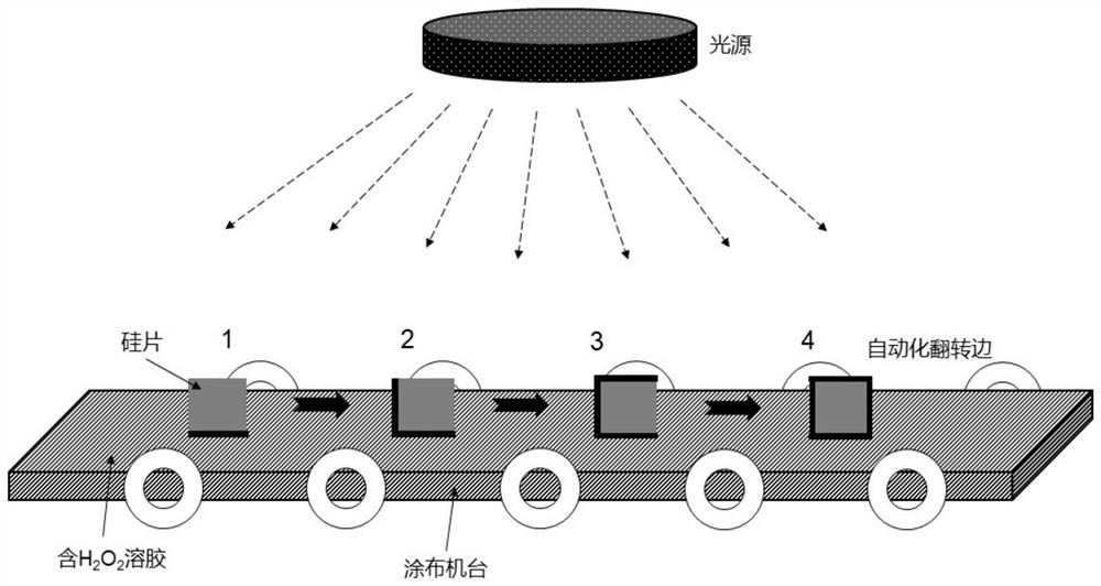
[0036] Embodiment 1 discloses a battery edge passivation method, which is used in the production process of the battery. This step can be considered to be arranged after the silicon substrate emitter junction is fabricated, and before the anti-reflection film and passivation film are prepared on the front and back, without affecting The other steps of battery fabrication are carried out. Specifically include the following steps:

[0037] A1: Preparation of oxidant (also photocatalyst), that is, slurry containing hydrogen peroxide, the main components are hydrogen peroxide, SiO 2 Powder and other ingredients. The details are as follows: first configure the 30 wt% H 2 o 2 solution 100 ml, and then continuously add SiO to the solution 2 15 g of powder (the particle size of the powder is 0.2 microns), until the gel is formed, and finally add 2 g of resin (binder) and stir evenly to form a slurry.

[0038] A2: After making the phosphorus emitter junction (or boron emitter junc...

Embodiment 2

[0043] Embodiment 2 discloses a battery edge passivation method for passivating the battery edge after cutting, which specifically includes the following steps:

[0044] B1: Preparation of oxidant (also photocatalyst), that is, slurry containing hydrogen peroxide, the main components are hydrogen peroxide, SiO 2 Powder and other ingredients. The details are as follows: first configure the 30 wt% H 2 o 2 solution 100 ml, and then continuously add SiO to the solution 2 15 g of powder (the particle size of the powder is 0.2 microns), until the gel is formed, and finally add 2 g of resin (binder) and stir evenly to form a slurry.

[0045] B2: Select a 156 mm*156 mm n-type monocrystalline silicon cell, and cut the cell by laser to form a half piece (also called a half piece). Of course, it can also be cut pieces such as one-third piece, one-quarter piece, ..., one-Nth piece.

[0046] B3: Place the above-mentioned cut battery half piece on the coating tape, the cutting edge is ...


PUM

PropertyMeasurementUnit
thicknessaaaaaaaaaa
thicknessaaaaaaaaaa
particle diameteraaaaaaaaaa

Abstract

The invention discloses a battery edge passivation method. The slurry is printed on the edge of the crystalline silicon battery to be passivated by coating, and the edge is irradiated with ultraviolet light, so that under the condition of photocatalytic oxidation, A silicon oxide passivation film is formed on the side; the slurry contains hydrogen peroxide and SiO 2 powder; after the silicon oxide passivation film is formed on all sides that need to be passivated on the crystalline silicon battery, annealing treatment is performed on the crystalline silicon battery that has completed photocatalytic oxidation. Further, the present invention also discloses the application of the above method. The invention utilizes the photocatalytic oxidation technology to passivate the edge of the crystalline silicon solar cell, thereby reducing electrical recombination and leakage at the edge of the cell, and improving the photoelectric conversion efficiency of the cell.

Description

technical field [0001] The invention belongs to the technical field of solar battery preparation, and in particular relates to a method for realizing passivation of battery edges. Background technique [0002] Single solar cells need to be made into modules and applied to photovoltaic systems through series and parallel connection. Since the recombination and leakage at the edge of the solar cell are relatively more serious than other areas of the cell, this will affect the electrical performance of the single solar cell and the module, and then affect the power generation performance (power generation, stability, reliability) of the photovoltaic system applied to it. sex, etc.). Therefore, it is necessary to electrically isolate and passivate the edge of the solar cell to reduce leakage and electrical recombination at the edge of the cell. [0003] At present, in the processing and manufacturing of crystalline silicon solar cells in the industry, chemical etching, laser e...

Claims


Application Information

Patent Timeline
Patent Type & Authority Patents(China)
IPC IPC(8): H01L31/18H01L31/068
CPCH01L31/1804H01L31/1868H01L31/068Y02E10/547Y02P70/50
Inventor 黄海冰吴智涵绪欣曹育红沈梦超张胜军张梦葛
Owner CHANGZHOU SHICHUANG ENERGY CO LTD
Learn More