
Cu-containing industrial sludge hazardous waste resourceful treatment system and treatment method thereof

A technology for industrial sludge and treatment systems, applied in sludge treatment, water/sludge/sewage treatment, chemical instruments and methods, etc., can solve problems such as waste of resources, and achieve the effect of high degree of automation and good operation effect.

Inactive Publication Date: 2020-06-26
SHANGHAI INST FOR DESIGN & RES ON ENVIRONMENTAL ENG
View PDF7 Cites 4 Cited by
  • Summary
  • Abstract
  • Description
  • Claims
  • Application Information

AI Technical Summary

Problems solved by technology

[0004] The technical problem to be solved by the present invention is: to overcome the deficiencies of the prior art, to provide a Cu-containing industrial sludge hazardous waste resource treatment system and its treatment method, so as to solve the problem of huge waste of resources in the treatment of copper-containing sludge in the past

Method used


Image

  • Cu-containing industrial sludge hazardous waste resourceful treatment system and treatment method thereof

Examples


Embodiment 1

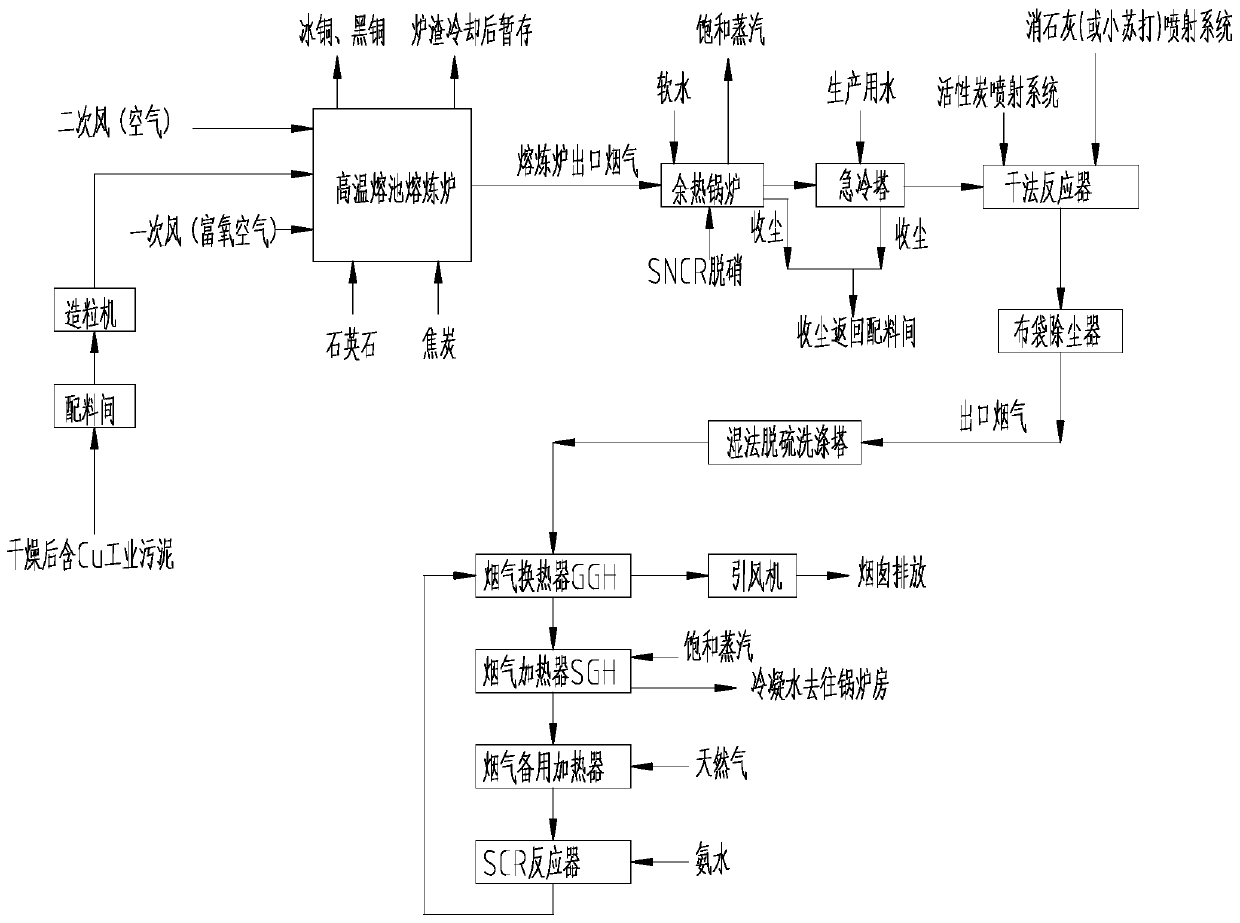
[0033] Such as figure 1 As shown, a hazardous waste resource treatment system containing Cu industrial sludge includes a batching room, a granulator, a smelting furnace, a waste heat boiler, and a flue gas treatment system.

[0034] Specifically, in this embodiment, the flue gas treatment system includes a quench tower, a dry reactor, a bag filter, a wet desulfurization scrubber, a flue gas heat exchanger, a flue gas heater, a flue gas backup heater, and an SCR reaction device;

[0035] The quench tower is connected to the dry reactor pipe, the dry reactor is connected to the bag filter, the bag filter is connected to the wet desulfurization scrubber, and the wet desulfurization scrubber exchanges heat with the flue gas The lumen of the flue gas heat exchanger communicates with the lumen of the flue gas backup heater, the lumen of the flue gas backup heater communicates with the SCR reactor pipeline, and the SCR reactor It communicates with the shell cavity pipeline of the f...

Embodiment 2

[0050] A method for recycling hazardous waste from industrial sludge containing Cu, using the system for recycling hazardous waste from industrial sludge containing Cu in Example 1, comprising the following steps:

[0051] Step S01, batching the Cu-containing industrial sludge in the batching room, and after controlling the humidity of the sludge to 35%, enter the granulator for granulation, so that the Cu industrial sludge becomes granular;

[0052] Step S02, adding granular Cu-containing industrial sludge into the smelting furnace, adding a slagging agent and a reducing agent, and entering the smelting furnace; the temperature in the smelting furnace is 1300°C, and 55% oxygen-enriched air is blown in at the same time;

[0053] The matte and black copper produced by smelting are used as products;

[0054] The water-quenched slag formed after the slag is water-cooled is used as a building material;

[0055] Step S03, the high-temperature flue gas produced by smelting is disch...


PUM


Abstract

The invention relates to a Cu-containing industrial sludge hazardous waste resourceful treatment system. The Cu-containing industrial sludge hazardous waste resourceful treatment system comprises a batching room, a granulator, a smelting furnace, a waste heat boiler and a flue gas treatment system. The invention relates to a Cu-containing industrial sludge hazardous waste resourceful treatment method, which comprises the following steps of: sequentially carrying out batching, granulation and sludge pyrometallurgy to obtain matte and black copper; cooling flue gas by the waste heat boiler, conducting SNCR denitration, quenching, dry deacidification, cloth bag dust removal, wet deacidification and SCR reactor desulfurization treatment, and then performing discharging. According to the invention, the Cu component in the sludge is recovered to the maximum extent through a reasonable ratio of the components entering the furnace, and the flue gas produced by a high temperature molten pool ispurified through the reference of a mature purification process of hazardous waste incineration flue gas and reasonable process optimization so as to meet the emission standard requirement and achieve up-to-standard emission.

Description

technical field [0001] The invention relates to the field of environmental protection, in particular to a hazardous waste resource treatment system and a treatment method for Cu-containing industrial sludge. Background technique [0002] my country is a big manufacturing country in the world, and the amount of industrial hazardous waste produced every year is huge. With the continuous development of the national industry, the industrial hazardous waste produced is still increasing. Some hazardous waste that cannot be disposed of by incineration, such as metal-containing substances, etc. At present, the main disposal method is to directly send it to the landfill for landfill after stabilization treatment, which not only occupies a large amount of land, but also has the risk of secondary pollution of the soil, and some valuable metals, after being disposed of by landfill, cause A huge waste of resources. [0003] Take the hazardous waste of process sludge with codes such as HW2...

Claims


Application Information

Patent Timeline
IPC IPC(8): C02F11/00B01J2/00B01D53/75B01D53/56B01D53/83B01D53/40B01D46/02B01D53/50C22B15/00C22B7/02C02F103/34
CPCC02F11/00B01J2/00B01D53/78B01D53/56B01D53/83B01D53/40B01D46/02B01D53/50C22B15/0056C02F2103/34B01D2251/2067B01D2258/0283Y02P10/20
Inventor 吴迪樊锐郭鹏辉刘玉坤
Owner SHANGHAI INST FOR DESIGN & RES ON ENVIRONMENTAL ENG
Learn More