
Surface-treated copper foil, and copper-clad laminate and printed wiring board using the surface-treated copper foil

A surface treatment, copper foil technology, applied in printed circuits, printed circuits, printed circuit manufacturing, etc., can solve the problems of increased transmission loss, insufficient transmission loss, and high transmission loss, and achieve good adhesion and laser processing. The effect of good, good high frequency characteristics

Active Publication Date: 2022-01-11
FURUKAWA ELECTRIC CO LTD +1
View PDF33 Cites 0 Cited by
  • Summary
  • Abstract
  • Description
  • Claims
  • Application Information

AI Technical Summary

Problems solved by technology

However, in this case, depending on the type of resin, there is a problem that it is difficult to obtain chemical adhesion even if a coupling agent is used.
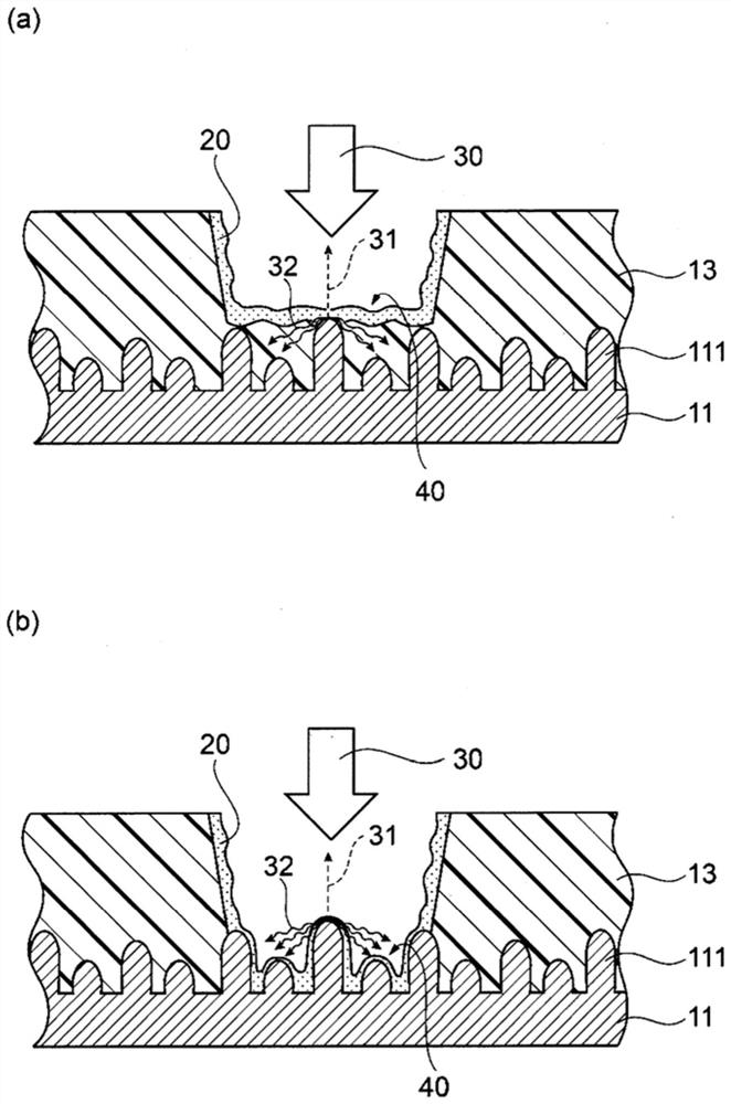
However, a laser absorbing layer or a blackened layer with high transmission loss remains at the interface between the resin base material and the copper foil other than the blind via hole
Therefore, the transmission loss increases, and the required level of lower transmission loss that has been demanded in recent years is not sufficiently achieved

Method used


Image

  • Surface-treated copper foil, and copper-clad laminate and printed wiring board using the surface-treated copper foil
  • Surface-treated copper foil, and copper-clad laminate and printed wiring board using the surface-treated copper foil
  • Surface-treated copper foil, and copper-clad laminate and printed wiring board using the surface-treated copper foil

Examples


Embodiment 1 to 10、 comparative example 1 to 7

[0142] In Example 1, the following steps [1] to [4] were performed to obtain a surface-treated copper foil. It will be described in detail below. It should be noted that, with regard to Examples 2 to 10 and Comparative Examples 1 to 7, in the formation step [2] of the roughened surface, as described in the above-mentioned Table 1, the roughening plating treatment (1) was set. Except for each condition, the surface-treated copper foil was obtained by the method similar to Example 1.

[0143] [1] Preparation of copper foil substrate

[0144] An electrolytic copper foil was prepared as a copper foil substrate to be a base material for roughening treatment. Electrodeposited copper foil was manufactured under the following conditions. In addition, the thickness and surface roughness of the electrodeposited copper foil manufactured under the following conditions are as follows.

[0145]

[0146] Cu: 80g / L

[0147] h 2 SO 4 : 70g / L

[0148] Chlorine concentration: 25mg / L

...


PUM

PropertyMeasurementUnit
heightaaaaaaaaaa
thicknessaaaaaaaaaa
surface roughnessaaaaaaaaaa

Abstract

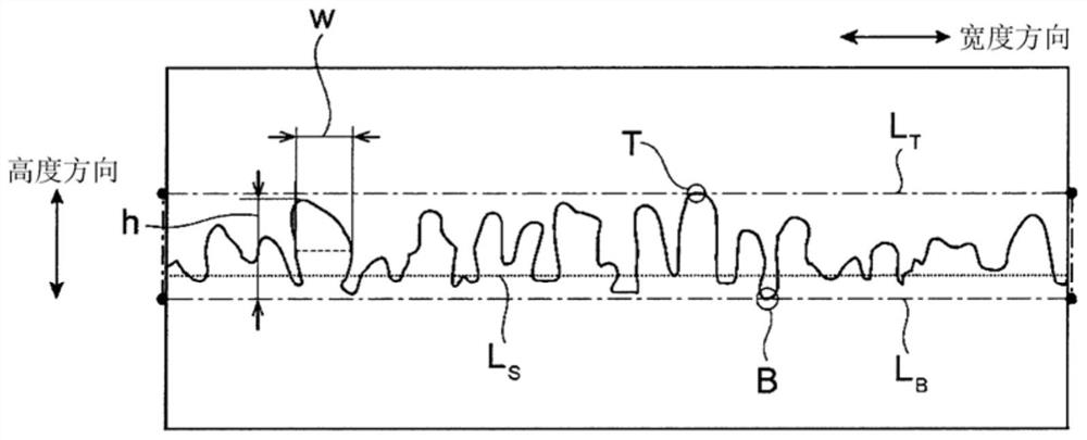
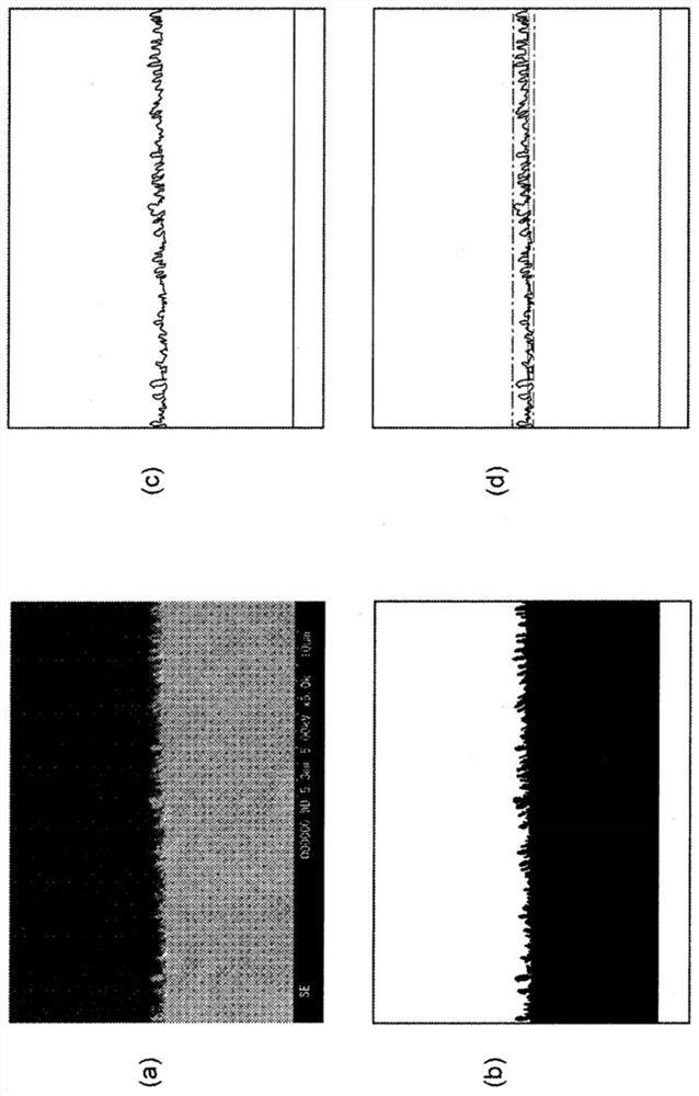
The title of the present invention is "a surface-treated copper foil, and a copper-clad laminate and a printed wiring board using the surface-treated copper foil". The surface-treated copper foil (11) of the present invention has a surface-treated coating including a roughened surface in which roughened particles (111) are formed on at least one surface of a copper foil base. When the cross-section of the surface-treated copper foil (11) is observed with a scanning electron microscope, the standard deviation of the particle height of the roughened particles (111) on the surface of the surface-treated coating is 0.16 μm or more and 0.30 μm or less, In addition, the average value of the ratio of the particle height to the particle width (particle height / particle width) of the roughened particles (111) is 2.30 or more and 4.00 or less.

Description

technical field [0001] The present invention relates to a surface-treated copper foil, in particular to a surface-treated copper foil suitable for printed circuit wiring boards used in high-frequency bands. Furthermore, this invention relates to the copper clad laminated board and printed wiring board which used the said surface-treated copper foil. Background technique [0002] In recent years, in order to cope with the improvement of the information processing speed of electronic equipment and high-speed wireless communication, etc., high-speed transmission of electrical signals is required in electronic circuit boards, and the application of high-frequency circuit boards is increasing. [0003] In high-frequency circuit boards, in order to transmit electrical signals at high speed, it is necessary to reduce transmission loss. As a method of reducing transmission loss, a method of reducing the dielectric constant and a low dielectric loss tangent of a resin base material,...

Claims


Application Information

Patent Timeline
Patent Type & Authority Patents(China)
IPC IPC(8): B32B15/20B32B15/08C25D7/06C25D1/04C25D5/16H05K1/03
CPCC25D1/04C25D3/38C25D7/0614C25D5/08C25D3/12C25D3/22C25D3/04C25D5/14H05K3/384H05K3/022H05K2201/0141H05K2203/0307B32B2457/08B32B2307/732B32B2307/734B32B2307/306B32B15/09B32B15/092B32B27/36B32B27/38B32B2255/06B32B27/285B32B2250/02B32B2255/205B32B2270/00B32B27/281B32B27/42B32B2264/102B32B2307/204B32B27/286B32B2264/108B32B15/098B32B27/20B32B27/288B32B15/08B32B15/20B32B2264/107H05K3/0035H05K3/427C25D5/627C25D5/605C25D5/611H05K1/09H05K1/0237H05K3/0064H05K3/429H05K3/4655H05K1/03C25D7/06
Inventor 宇野岳夫奥野裕子鹤田隆宏西芳正福武素直
Owner FURUKAWA ELECTRIC CO LTD
Learn More