
Method for preparing coating by 3D printing overlapping electron beam

A 3D printing and electron beam technology, applied in coating, metal material coating process, additive manufacturing, etc., can solve the problems of low powder utilization rate, low forming precision, low forming precision, etc., and achieve low cost and smooth surface The effect of flatness and good forming precision

Inactive Publication Date: 2020-01-21
FUJIAN UNIV OF TECH
View PDF10 Cites 5 Cited by
  • Summary
  • Abstract
  • Description
  • Claims
  • Application Information

AI Technical Summary

Problems solved by technology

It solves the problems of low molding precision and low powder utilization rate in the prior art, and avoids the conventional problem of requiring more auxiliary powder and limited size
[0003] The relevant patents are as follows: publication number: CN 107225245 A; patent name: metal powder 3D laser forming powder coating device and forming method; and application number: CN 201811514812.2; patent name: a combination of pre-set layer and ultrasound to enhance the coating Bonding force method and application number: CN201210097330.8; patent name: method of presetting powder by extrusion method for laser cladding to obtain composite coating; CN201910476904.4; patent name: a cemented carbide-diamond composite material and its Preparation method; CN 109396441 A; patent name: a heat treatment method for electron beam welding laser selective melting forming parts; CN109295343 A; patent name: a titanium alloy gear and its preparation method; the existing composite coating in the above patent documents The preparation method of the composite coating, under the action of external load or thermal stress, is easy to peel off the coating, coating peeling, bubbling or cracking, etc., and the problem of low molding accuracy will increase the cost virtually.

Method used


Image

  • Method for preparing coating by 3D printing overlapping electron beam
  • Method for preparing coating by 3D printing overlapping electron beam
  • Method for preparing coating by 3D printing overlapping electron beam

Examples


Embodiment Construction

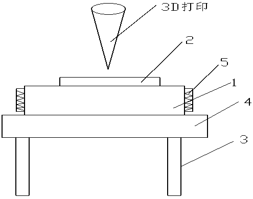
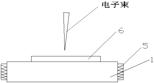
[0017] The method of the present invention is used for 3D printing overlapping electron beams to prepare a coating. Metal or ceramic powder, metal / ceramic powder is mixed into a paste or paste and printed on the surface of the substrate 1 layer by layer through 3D printing. The three-dimensional model is carried out according to the set layer thickness, and then the metal or ceramic powder on the surface of the substrate, and the metal / ceramic powder is mixed into a paste or paste to preheat to form a fused layer 2. The heating device used for this preheating Comprising a high-frequency vibrator 4 and an induction heating coil 5 placed on a workbench 3, the high-frequency vibrator 4 acts on the bottom of the deposited layer 2 and the substrate 1, and the substrate is surrounded by an induction heating coil 5 as preheating, and after preheating, electron beams are used to melt the fused layer to form a metal / ceramic composite gradient coating 6, and finally the metal / ceramic com...


PUM

PropertyMeasurementUnit
Thicknessaaaaaaaaaa
Thicknessaaaaaaaaaa
Thicknessaaaaaaaaaa

Abstract

The invention relates to a method for preparing a coating by 3D printing overlapping an electron beam. Metal or ceramic powder and metal / ceramic powder are printed on the surface of a base material layer by layer through 3D printing, layer-by-layer printing is carried out by a three-dimensional model according to the set layer thickness, and then the metal or ceramic powder and metal / ceramic powder on the surface of the base material are preheated to form a fusion layer. A heating device used for the preheating includes a high-frequency vibrator and an induction heating coil which are placed on a workbench, the high-frequency vibrator acts on the bottoms of the fusion layer and the base material, the induction heating coil is arranged around the base material for preheating, after preheating is carried out, the fusion layer is melted with the electron beam to form a metal / ceramic. composite coating, and finally the metal / ceramic composite coating is subjected to post-heat treatment through the induction heating coil. The product development cycle is greatly shortened, production rate is improved, and the production cost is reduced.

Description

Technical field: [0001] The invention relates to a method for preparing a coating by 3D printing overlapping electron beams. Background technique: [0002] Laser 3D printing technology is a major breakthrough in manufacturing technology in the past two decades, and its influence on manufacturing can be compared with that of CNC machine tools in the middle of the 20th century. Laser 3D printing technology can directly and quickly manufacture complex functional parts. It has great competitive advantages in material selection, design freedom, and product development. It can also greatly shorten the processing cycle and greatly reduce the time for manufacturing preparation and data conversion. Compared with traditional material cutting and forming, the additive manufacturing method represented by this technology is a major innovation. 3D printing manufacturing technology is a near-net-shaping technology. The size of the printed parts is very close to the final product. Compared...

Claims


Application Information

Patent Timeline
IPC IPC(8): C23C24/10B22F3/105B22F7/04B33Y10/00
CPCC23C24/103C23C24/10B22F7/04B33Y10/00B22F2007/042B22F10/00B22F10/34B22F10/28B22F12/13B22F10/50Y02P10/25
Inventor 简明德黄卫东练国富刘成武书铁平
Owner FUJIAN UNIV OF TECH
Learn More